
Page 858 - Mechatronics with Experiments
P. 858
844 MECHATRONICS
1
z
Unit delay
State
Input
Output
Reset 1
s
Initial condition Saturation
Integrator
(a) (b)
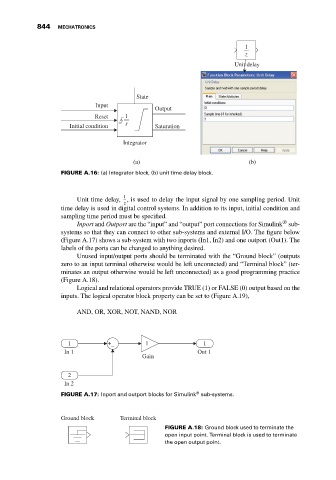
FIGURE A.16: (a) Integrator block, (b) unit time delay block.
1
Unit time delay, , is used to delay the input signal by one sampling period. Unit
z
time delay is used in digital control systems. In addition to its input, initial condition and
sampling time period must be specified.
®
Inport and Outport are the “input” and “output” port connections for Simulink sub-
systems so that they can connect to other sub-systems and external I/O. The figure below
(Figure A.17) shows a sub-system with two inports (In1, In2) and one outport (Out1). The
labels of the ports can be changed to anything desired.
Unused input/output ports should be terminated with the “Ground block” (outputs
zero to an input terminal otherwise would be left unconncted) and “Terminal block” (ter-
minates an output otherwise would be left unconnected) as a good programming practice
(Figure A.18).
Logical and relational operators provide TRUE (1) or FALSE (0) output based on the
inputs. The logical operator block property can be set to (Figure A.19),
AND, OR, XOR, NOT, NAND, NOR
1 + 1 1
–
In 1 Out 1
Gain
2
In 2
®
FIGURE A.17: Inport and outport blocks for Simulink sub-systems.
Ground block Terminal block
FIGURE A.18: Ground block used to terminate the
open input point. Terminal block is used to terminate
the open output point.