
Page 110 - Servo Motors and Industrial Control Theory -
P. 110
104 6 AC Servo Motors
R 1 X j X j
2
1
I 1 I w I 0 I m I 2
V 1 SIN(ωt) R m X j R 2 t
m
S
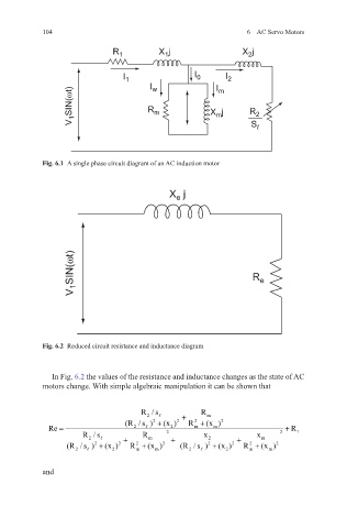
Fig. 6.1 A single phase circuit diagram of an AC induction motor
X j
e
V 1 SIN(ωt) R e
Fig. 6.2 Reduced circuit resistance and inductance diagram
In Fig. 6.2 the values of the resistance and inductance changes as the state of AC
motors change. With simple algebraic manipulation it can be shown that
R /s R
2 + m
2
2
(R / s ) + (x ) 2 R + (x ) 2
Re = 2 2 2 m m 2 + R 1
R /s + R m + x 2 + x m
2
(R / s ) + (x ) 2 R + (x ) 2 (R / s ) + (x ) 2 R + (x ) 2
2
2
2
2
m
m
2
m
2
m
2
2
and