
Page 111 - Servo Motors and Industrial Control Theory -
P. 111
6.3 Mathematical Model 105
80
72
64 f = 65 f = 75
RESISTANCE (OHMS) 48 f = 35 f = 45
56
f = 55
40
32
f = 25
24
f = 15
16
8 f = 5
0
0 6 12 18 24 30 36 42 48 54 60
TORQUE (N–M)
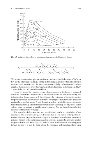
Fig. 6.3 Variations of the effective resistance as load and supplied frequency change
x 2 + x m
(R / s ) + x 2 R + x 2
2
2
x = 2 2 m m + x
e 2 2 1
R /s R x x
2 + m + 2 + m
(R / s ) + x 2 R + x 2 (R / s ) + x 2 R + x 2
2
2
2
2
2 2 m m 2 2 m m
The above two equations give the equivalent resistance and inductance of AC mo-
tors as the operating conditions of the motor changes. It shows that the effective
resistance and inductance of the motor are function of slip ratio s ℓ (torque) and the
supplied frequency. To study the variations of resistance and inductance a 2.2 KW
3 phase induction AC motor is considered.
Figure 6.3 shows the variation of equivalent resistance as the torque is increased
at various frequencies. It shows that at no load conditions the resistance is very low
indicating that larger current will flow through the resistance of the motor. As the
torque is increased, the resistance increases, reaching to a maximum and it reduces
again at large applied torque. It also shows that at low supplied frequency the resis-
tance reduces rapidly. This is the reason that at low frequency the amplitude of the
voltage must be reduced to avoid excessive current flowing through the effective
resistance of the motor windings.
The equivalent inductance can also be calculated similar to calculation of the
resistance. This is shown in Fig. 6.4. It shows that at low values of torque the in-
ductance is very large and when the torque is increased the equivalent inductance
reduces. The rate of the inductance reduction as torque increased is greater when the
frequency is reduced. Both Figs. 6.3 and 6.4 show that there is an operating point
for AC motors. It is also the point where the resistance and inductance have such