
Page 115 - Servo Motors and Industrial Control Theory -
P. 115
6.4 Frequency Converter 109
OUTPUT FREQUENCY (Hz)
60
54
48
*
42 * * *
36 * * *
* *
30 * * *
24 * * * *
18 * * * *
12 * * * *
6 * * * *
0 * *
0 1.6 3.2 4.8 6.4 8
INPUT ERROR VOLTAGE (VOLT9)
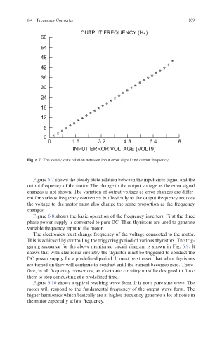
Fig. 6.7 The steady state relation between input error signal and output frequency
Figure 6.7 shows the steady state relation between the input error signal and the
output frequency of the motor. The change to the output voltage as the error signal
changes is not shown. The variation of output voltage as error changes are differ-
ent for various frequency converters but basically as the output frequency reduces
the voltage to the motor must also change the same proportion as the frequency
changes.
Figure 6.8 shows the basic operation of the frequency inverters. First the three
phase power supply is converted to pure DC. Then thyristors are used to generate
variable frequency input to the motor.
The electronics must change frequency of the voltage connected to the motor.
This is achieved by controlling the triggering period of various thyristors. The trig-
gering sequence for the above mentioned circuit diagram is shown in Fig. 6.9. It
shows that with electronic circuitry the thyristor must be triggered to conduct the
DC power supply for a predefined period. It must be stressed that when thyristors
are turned on they will continue to conduct until the current becomes zero. There-
fore, in all frequency converters, an electronic circuitry must be designed to force
them to stop conducting at a predefined time.
Figure 6.10 shows a typical resulting wave form. It is not a pure sine wave. The
motor will respond to the fundamental frequency of the output wave form. The
higher harmonics which basically are at higher frequency generate a lot of noise in
the motor especially at low frequency.