Page 117 - Servo Motors and Industrial Control Theory -
P. 117

6.4   Frequency Converter                                       111

                     Vm
                          TH1 on  TH4 on     V 4
                                                                       ωt
                         0     180°    360°
                     Vsn
                          TH3  TH3 on  TH6 on
                           on                                          ωt
                         0   120°   300°
                     Vtn
                             TH2 on  TH5 on  TH2 on
                                                                       ωt
                         0 60°    240°

                    Vrs
                  -Vsn-Vrn
                                180° 300°  V 4
                                                                       ωt
                         0   120°      360°

                    Vst
                  -Vsn-Vtn
                                                                       ωt

                    Vtr
                  -Vtn-Vm

                                                                       ωt

                  Thyristor
                   gating
                 sequence  TH2  TH4  TH6  TH2
                        TH1 TH3   TH5  TH1  TH3

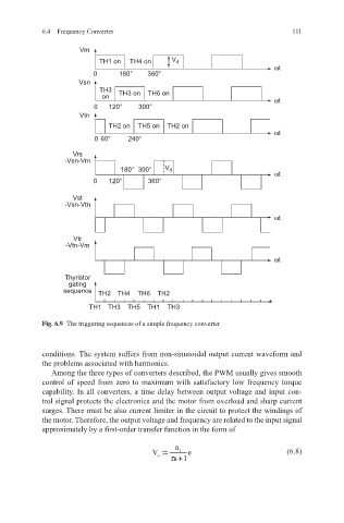
            Fig. 6.9   The triggering sequences of a simple frequency converter


            conditions. The system suffers from non-sinusoidal output current waveform and
            the problems associated with harmonics.
              Among the three types of converters described, the PWM usually gives smooth
            control of speed from zero to maximum with satisfactory low frequency torque
            capability. In all converters, a time delay between output voltage and input con-
            trol signal protects the electronics and the motor from overload and sharp current
            surges. There must be also current limiter in the circuit to protect the windings of
            the motor. Therefore, the output voltage and frequency are related to the input signal
            approximately by a first-order transfer function in the form of
                                              a
                                        V:=    1  e                       (6.8)
                                         o  τ +
                                             s1
   112   113   114   115   116   117   118   119   120   121   122