
Page 121 - Servo Motors and Industrial Control Theory -
P. 121
116 7 Electrohydraulic Servo Motors
P 0 P S P 0
X
A
e a
B q
b y
M
c
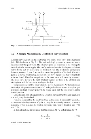
Fig. 7.1 A simple mechanically controlled hydraulic position control
7.2 A Simple Mechanically Controlled Servo System
A simple servo system can be constructed by a simple spool valve and a hydraulic
jack. This is shown in Fig. 7.1. The hydraulic high pressure is connected to the
middle port of the spool valve. The other two ports are connected to the return path
to the hydraulic power supply. The configurations shown in the diagram both inlet
valves to the jack are closed and the load is at rest. The mechanical connections
between points A, B, and C are used to control the position of the load. When the
point B is moved by amount e, the jack will not move because the two ports at both
ends are closed. Therefore, the point A on the spool valve will move by amount x.
The spool valve moves to the right. The high pressure oil flows to the left hand side
of the piston and the load starts moving to the right.
The position of point B is fixed when it is moved by amount e. As the load moves
to the right, the point A moves to the left and spool valve moves to its original po-
sition and the high pressure port will be closed again and the load stopped at the
desired position.
Using the principle of superposition, a relation between the three displacements
x, e, and y may be obtained.
First, it is assumed that the point C is fixed and the point B is moved by amount e.
As a result of the displacement of point B, the point A moves by amount x. From the
similarity of two triangles, the relation between x and e can be found in Eqs. (7.1)
and (7.2).
In this calculation, it is assumed that the distance AB = a and distance BC = b
e : = b (7.1)
x ab+
which can be written as,