
Page 125 - Servo Motors and Industrial Control Theory -
P. 125
120 7 Electrohydraulic Servo Motors
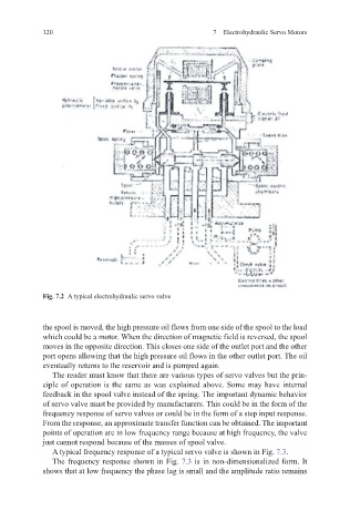
Fig. 7.2 A typical electrohydraulic servo valve
the spool is moved, the high pressure oil flows from one side of the spool to the load
which could be a motor. When the direction of magnetic field is reversed, the spool
moves in the opposite direction. This closes one side of the outlet port and the other
port opens allowing that the high pressure oil flows in the other outlet port. The oil
eventually returns to the reservoir and is pumped again.
The reader must know that there are various types of servo valves but the prin-
ciple of operation is the same as was explained above. Some may have internal
feedback in the spool valve instead of the spring. The important dynamic behavior
of servo valve must be provided by manufacturers. This could be in the form of the
frequency response of servo valves or could be in the form of a step input response.
From the response, an approximate transfer function can be obtained. The important
points of operation are in low frequency range because at high frequency, the valve
just cannot respond because of the masses of spool valve.
A typical frequency response of a typical servo valve is shown in Fig. 7.3.
The frequency response shown in Fig. 7.3 is in non-dimensionalized form. It
shows that at low frequency the phase lag is small and the amplitude ratio remains