
Page 126 - Servo Motors and Industrial Control Theory -
P. 126
7.4 Hydraulic Servo Motors 121
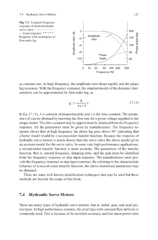
Fig. 7.3 A typical frequency
response of electrohydraulic
servo valve. - - - - - - - - - - - 200
- - Exact response. * * * * * 0
Amplitude ratio -db –4 120 Phase angle-deg
Response with assumption of Amplitude 150
first-order lag –2 ratio
–8
angle
40
–16 Phase x x 80
5 10 20 50 100 200 500
Frequency HZ
as constant one. At high frequency, the amplitude ratio drops rapidly and the phase
lag increases. With the frequency response, the simplest model of the dynamic char-
acteristic can be approximated by first-order lag, as
A
q: = v (7.13)
s +1τ
In Eq. (7.13), A is constant of proportionality and τ is the time constant. The param-
eter ( A) can be obtained by knowing the flow rate for a given voltage supplied to the
torque motor. The time constant may be approximately obtained from the frequency
response. All the parameters must be given by manufacturers. The frequency re-
sponse shows that at high frequency the phase lag goes above 90° indicating that
a better model would be a second-order transfer function. Because the response of
hydraulic servo motors is much slower than the servo valve the above model gives
an accurate model for the servo valve. In some very high performance applications,
a second-order transfer function is more accurate. The parameters of the transfer
function, that is, natural frequency, damping ratio, and the gain must be identified
from the frequency response or step input response. The manufacturers must pro-
vide the frequency response or step input response. By referring to the characteristic
behavior of a second-order transfer function, the above mentioned parameters may
be obtained.
There are some well known identification techniques that may be used but these
methods are beyond the scope of this book.
7.4 Hydraulic Servo Motors
There are many types of hydraulic servo motors, that is, radial, gear, and axial pis-
ton types. In high performance systems, the axial type with constant flow delivery is
commonly used. This is because of its excellent accuracy and low mass/power ratio