
Page 130 - Servo Motors and Industrial Control Theory -
P. 130
7.5 A Numerical Investigation of the Transient Behavior … 125
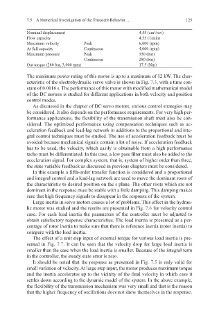
Nominal displacement 4.55 (cm /rev)
3
Flow capacity 4.55 (1/min)
Maximum velocity Peak 6,000 (rpm)
At full capacity Continuous 4,000 (rpm)
Maximum pressure Peak 350 (bar)
Continuous 280 (bar)
Out torque (280 bar, 3,000 rpm) 17.5 (Nm)
The maximum power rating of this motor is up to a maximum of 12 kW. The char-
acteristic of the electrohydraulic servo valve is shown in Fig. 7.3, with a time con-
stant of 0.0016 s. The performance of this motor with modified mathematical model
of the DC motors is studied for different applications in both velocity and position
control modes.
As discussed in the chapter of DC servo motors, various control strategies may
be considered. It also depends on the performance requirements. For very high per-
formance applications, the flexibility of the transmission shaft must also be con-
sidered. The optimized performance using compensation techniques such as ac-
celeration feedback and lead-lag network in additions to the proportional and inte-
gral control techniques must be studied. The use of acceleration feedback must be
avoided because mechanical signals contain a lot of noise. If acceleration feedback
has to be used, the velocity, which easily is obtainable from a high performance
tacho must be differentiated. In this case, a low pass filter must also be added to the
acceleration signal. For complex system, that is, system of higher order than three,
the state variable feedback as discussed in previous chapters must be considered.
In this example a fifth-order transfer function is considered and a proportional
and integral control and a lead-lag network are used to move the dominant roots of
the characteristic to desired position on the s plane. The other roots which are not
dominant in the response must be stable with a little damping. This damping makes
sure that high frequency signals to disappear in the response of the system.
Large inertia in servo motors causes a lot of problems. This effect in the hydrau-
lic motor was studied and the results are presented in Fig. 7.6 for velocity control
case. For each load inertia the parameters of the controller must be adjusted to
obtain satisfactory response characteristics. The load inertia is presented as a per-
centage of rotor inertia to make sure that there is reference inertia (rotor inertia) to
compare with the load inertia.
The effect of a unit step input of external torque for various load inertia is pre-
sented in Fig. 7.7. It can be seen that the velocity drop for large load inertia is
smaller than the case when the load inertia is smaller. Because of the integral term
in the controller, the steady state error is zero.
It should be noted that the response as presented in Fig. 7.5 is only valid for
small variation of velocity. At large step input, the motor produces maximum torque
and the inertia accelerates up to the vicinity of the final velocity in which case it
settles down according to the dynamic model of the system. In the above example,
the flexibility of the transmission mechanism was very small and that is the reason
that the higher frequency of oscillations does not show themselves in the response.