
Page 127 - Servo Motors and Industrial Control Theory -
P. 127
122 7 Electrohydraulic Servo Motors
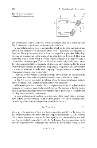
Fig. 7.4 Schematic diagram
of an axial piston type motor C B
D A
E
and performance. Figure 7.4 shows a schematic diagram of an axial piston type and
Fig. 7.5 shows its typical static performance characteristic.
In an axial piston type, there is a swash plate which controls the maximum speed
of the motor because every revolution of the rotor is equivalent to a specified oil
flow rate. Usually the swash plate is fixed for a specific application. When high
pressure oil is connected to the inlet port, an axial force is developed. This force
causes the rotor to rotate. When a reverse rotation is required, the high pressure is
connected to the other input. This is achieved by an electrohydraulic servo valve.
To reduce compressibility of hydraulic oil, the servo valve is attached to the motor
with minimum distance. To understand the principle of operation of a servo motor,
it is better to think how it can be used as a pump. The operation can be imagined as
high pressure is connected to the motor.
There are several pistons in axial piston type servo motors. To understand the
principle of operation, only two pistons at two extreme positions are shown.
In Fig. 7.5, several parameters are plotted where the important characteristics to
notice are speed-torque characteristic and the overall efficiency
Although the principal behavior of the axial piston type motor is explained, other
hydraulic servo motors have similar static behavior. The purpose is that the readers
have an understanding of hydraulic servo motors and to guide what to look for when
deciding to use hydraulic servo motors.
In most applications of machine tools, the angle of the swash plate is kept con-
stant and the flow is controlled via an electrohydraulic servo valve. In steady state,
the velocity of the motor will depend on the oil flow rate to it:
q : C · = ω (7.14)
m m m
where q is the variation of flow rate from an operating point C is the motor dis-
m
m
placement (volume of oil displaced by one complete rotation) and ω is the velocity
m
of the motor. In order to complete the flow equation, the compressibility and leak-
age flow must also be added to Eq. (7.14).The leakage flow is proportional to the
pressure difference between the inlet and outlet of the motor which usually is zero:
q : =λ (7.15)
·p
1 m