
Page 137 - Servo Motors and Industrial Control Theory -
P. 137
132 8 Actuators Based on Electro-Rheological Fluid
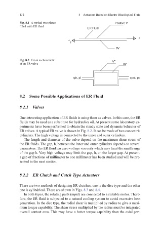
Fig. 8.1 A typical two plates Positive V
filled with ER fluid
ER Fluid
+ F
F
0V
Fig. 8.2 Cross section view V +
of an ER valve 0V
qin, pi qout, po
8.2 Some Possible Applications of ER Fluid
8.2.1 Valves
One interesting application of ER fluids is using them as valves. In this case, the ER
fluids may be used as a substitute for hydraulics oil. At present some laboratory ex-
periments have been performed to obtain the steady state and dynamic behavior of
ER valves. A typical ER valve is shown in Fig. 8.2. It can be made of two concentric
cylinders. The high voltage is connected to the inner and outer cylinders.
The length and diameter of the valve depend on the maximum shear stress of
the ER fluids. The gap, h, between the inner and outer cylinders depends on several
parameters. The ER fluid has zero voltage viscosity which may limit the small range
of the gap h. Very high voltage may limit the gap, h, on the larger gap. At present,
a gap of fractions of millimeter to one millimeter has been studied and will be pre-
sented in the next section.
8.2.2 ER Clutch and Catch Type Actuators
There are two methods of designing ER clutches, one is the disc type and the other
one is cylindrical. These are shown in Figs. 8.3 and 8.4.
In both types, the rotating parts (input) are connected to a suitable motor. There-
fore, the ER fluid is subjected to a natural cooling system to avoid excessive heat
generation. In the disc type, the radial shear is multiplied by radius to give a maxi-
mum torque capability. The shear stress multiplied by the radius must be integrated
overall contact area. This may have a better torque capability than the axial part.