
Page 166 - Servo Motors and Industrial Control Theory -
P. 166
162 Appendix A
Also determine the absolute flow rate at back pressure of 50 bars and valve open-
ing of X = 3 mm.
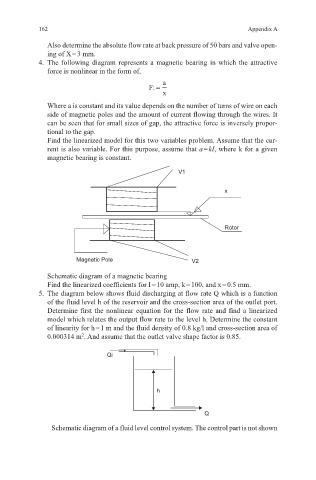
4. The following diagram represents a magnetic bearing in which the attractive
force is nonlinear in the form of,
a
F: =
x
Where a is constant and its value depends on the number of turns of wire on each
side of magnetic poles and the amount of current flowing through the wires. It
can be seen that for small sizes of gap, the attractive force is inversely propor-
tional to the gap.
Find the linearized model for this two variables problem. Assume that the cur-
rent is also variable. For this purpose, assume that a = kI, where k for a given
magnetic bearing is constant.
V1
x
Rotor
Magnetic Pole V2
Schematic diagram of a magnetic bearing
Find the linearized coefficients for I = 10 amp, k = 100, and x = 0.5 mm.
5. The diagram below shows fluid discharging at flow rate Q which is a function
of the fluid level h of the reservoir and the cross-section area of the outlet port.
Determine first the nonlinear equation for the flow rate and find a linearized
model which relates the output flow rate to the level h. Determine the constant
of linearity for h = 1 m and the fluid density of 0.8 kg/l and cross-section area of
0.000314 m . And assume that the outlet valve shape factor is 0.85.
2
Qi
h
Q
Schematic diagram of a fluid level control system. The control part is not shown