
Page 169 - Servo Motors and Industrial Control Theory -
P. 169
Appendix A 165
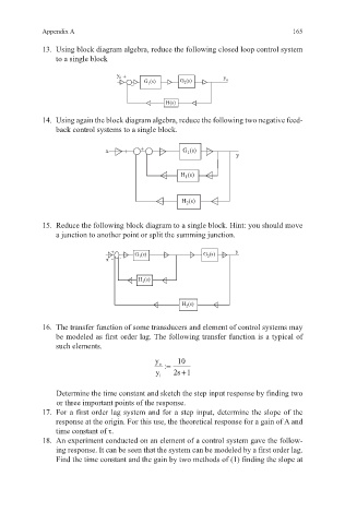
13. Using block diagram algebra, reduce the following closed loop control system
to a single block
y + y o
i
1
2
– G (s) G (s)
H(s)
14. Using again the block diagram algebra, reduce the following two negative feed-
back control systems to a single block.
x + + G 1 (s)
– – y
H 1 (s)
H (s)
2
15. Reduce the following block diagram to a single block. Hint: you should move
a junction to another point or split the summing junction.
+ (s) G (s) y
x - - G 1 2
H (s)
1
H (s)
2
16. The transfer function of some transducers and element of control systems may
be modeled as first order lag. The following transfer function is a typical of
such elements.
y o := 10
+
y 2 s 1
i
Determine the time constant and sketch the step input response by finding two
or three important points of the response.
17. For a first order lag system and for a step input, determine the slope of the
response at the origin. For this use, the theoretical response for a gain of A and
time constant of τ.
18. An experiment conducted on an element of a control system gave the follow-
ing response. It can be seen that the system can be modeled by a first order lag.
Find the time constant and the gain by two methods of (1) finding the slope at