
Page 174 - Servo Motors and Industrial Control Theory -
P. 174
170 Appendix A
where,
K := 1000
p
K := 50
i
K := 20
d
It should be noted that the gain of derivative cannot be selected too large be-
cause it will amplify the noise. Hint: design three separate OP-AMPs to give
the gain of three terms separately and then design a Summation junction to add
the three terms together.
31. In problem 24, with only proportional controller there will be always a steady
state error. In order to achieve zero steady state error, an integral must be added
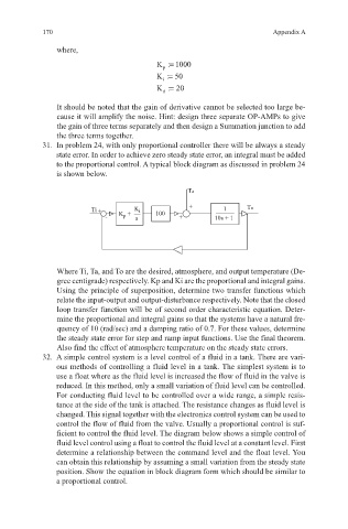
to the proportional control. A typical block diagram as discussed in problem 24
is shown below.
Ta
+
Ti + K p + K i 100 1 To
- s + 10s + 1
Where Ti, Ta, and To are the desired, atmosphere, and output temperature (De-
gree centigrade) respectively. Kp and Ki are the proportional and integral gains.
Using the principle of superposition, determine two transfer functions which
relate the input-output and output-disturbance respectively. Note that the closed
loop transfer function will be of second order characteristic equation. Deter-
mine the proportional and integral gains so that the systems have a natural fre-
quency of 10 (rad/sec) and a damping ratio of 0.7. For these values, determine
the steady state error for step and ramp input functions. Use the final theorem.
Also find the effect of atmosphere temperature on the steady state errors.
32. A simple control system is a level control of a fluid in a tank. There are vari-
ous methods of controlling a fluid level in a tank. The simplest system is to
use a float where as the fluid level is increased the flow of fluid in the valve is
reduced. In this method, only a small variation of fluid level can be controlled.
For conducting fluid level to be controlled over a wide range, a simple resis-
tance at the side of the tank is attached. The resistance changes as fluid level is
changed. This signal together with the electronics control system can be used to
control the flow of fluid from the valve. Usually a proportional control is suf-
ficient to control the fluid level. The diagram below shows a simple control of
fluid level control using a float to control the fluid level at a constant level. First
determine a relationship between the command level and the float level. You
can obtain this relationship by assuming a small variation from the steady state
position. Show the equation in block diagram form which should be similar to
a proportional control.