
Page 8 - 3-5kV Induction Motor
P. 8
Data Analysis and Information Output
Iris Power is foremost focused on providing a clear, reliable and repeatable result that allows the user to understand the true condition of the motor
or motor and to make educated decisions for operations and maintenance. The PDTracII instrument has been designed to autonomously collect
partial discharge data on a continuous basis and output the relevant information needed to provide a decisive means of:
› Identifying Partial Discharge Severity
› Identifying Probable Causes of Deterioration
› Comparing Relative Health Across Equipment
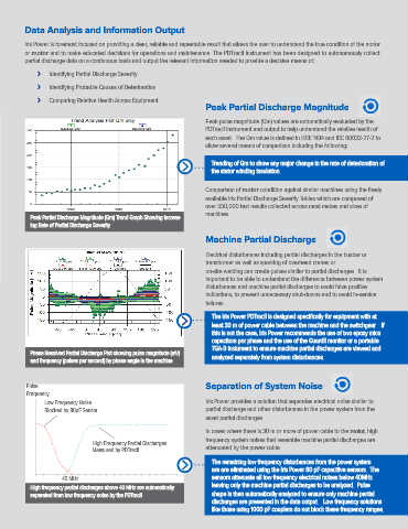
Peak Partial Discharge Magnitude
Peak pulse magnitude (Qm) values are automatically evaluated by the
PDTracII instrument and output to help understand the relative health of
each asset. The Qm value is defined in IEEE 1434 and IEC 60032-27-2 to
allow several means of comparison including the following:
Trending of Qm to show any major change in the rate of deterioration of
the stator winding insulation.
Comparison of motor condition against similar machines using the freely
available Iris Partial Discharge Severity Tables which are composed of
over 550,000 test results collected across most makes and sizes of
machines.
Peak Partial Discharge Magnitude (Qm) Trend Graph Showing Increas-
ing Rate of Partial Discharge Severity
Machine Partial Discharge
Electrical disturbances including partial discharges in the busbar or
transformer as well as sparking of overhead cranes or
on-site welding can create pulses similar to partial discharges. It is
important to be able to understand the difference between power system
disturbances and machine partial discharges to avoid false positive
indications, to prevent unnecessary shut-downs and to avoid in-service
failures.
The Iris Power PDTracII is designed specifically for equipment with at
least 30 m of power cable between the machine and the switchgear. If
this is not the case, Iris Power recommends the use of two epoxy mica
capacitors per phase and the use of the GuardII monitor or a portable
TGA-B instument to ensure machine partial discharges are viewed and
Phase Resolved Partial Discharge Plot showing pulse magnitude (mV) analyzed separately from system disturbances.
and frequency (pulses per second) by phase angle in the machine
Pulse Separation of System Noise
Frequency
60 Iris Power provides a solution that separates electrical noise similar to
Low Frequency Noise
50 Blocked by 80pF Sensor partial discharge and other disturbances in the power system from the
asset partial discharges.
40
In cases where there is 30 m or more of power cable to the motor, high
30 frequency system noises that resemble machine partial discharges are
High Frequency Partial Discharges
20 Measured by PDTracII attenuated by the power cable.
10 The remaining low frequency disturbances from the power system
are are eliminated using the Iris Power 80 pF capacitive sensors. The
0 sensors attenuate all low frequency electrical noises below 40MHz
40 MHz
0 5 10 15 20 25 30 35 40 45 50 55 60 65 70 75 80 85 90 95100 leaving only the machine partial discharges to be analyzed. Pulse
High frequency partial discharges above 40 MHz are automatically
separated from low frequency noise by the PDTracII shape is then automatically analyzed to ensure only machine partial
discharges are presented in the data output. Low frequency solutions
like those using 1000 pF couplers do not block these frequency ranges.