
Page 45 - GuardII+ Series 4208 Platform Flux User Manual
P. 45
User Instructions
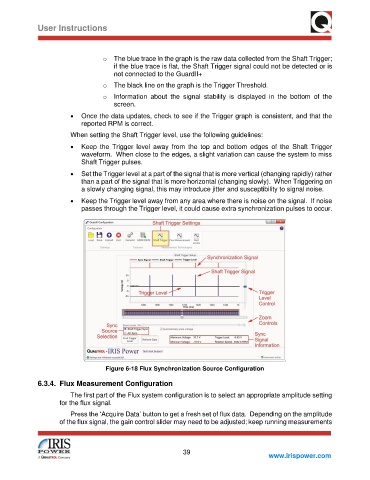
o The blue trace in the graph is the raw data collected from the Shaft Trigger;
if the blue trace is flat, the Shaft Trigger signal could not be detected or is
not connected to the GuardII+
o The black line on the graph is the Trigger Threshold.
o Information about the signal stability is displayed in the bottom of the
screen.
• Once the data updates, check to see if the Trigger graph is consistent, and that the
reported RPM is correct.
When setting the Shaft Trigger level, use the following guidelines:
• Keep the Trigger level away from the top and bottom edges of the Shaft Trigger
waveform. When close to the edges, a slight variation can cause the system to miss
Shaft Trigger pulses.
• Set the Trigger level at a part of the signal that is more vertical (changing rapidly) rather
than a part of the signal that is more horizontal (changing slowly). When Triggering on
a slowly changing signal, this may introduce jitter and susceptibility to signal noise.
• Keep the Trigger level away from any area where there is noise on the signal. If noise
passes through the Trigger level, it could cause extra synchronization pulses to occur.
Figure 6-18 Flux Synchronization Source Configuration
6.3.4. Flux Measurement Configuration
The first part of the Flux system configuration is to select an appropriate amplitude setting
for the flux signal.
Press the ‘Acquire Data’ button to get a fresh set of flux data. Depending on the amplitude
of the flux signal, the gain control slider may need to be adjusted; keep running measurements
39
www.irispower.com