Page 1023 - Master Catalog 2017, Inch
P. 1023

Copy Mills • M270  Series
                                                                                                              ™
                                                                                 Additional Application Advice • M270 Ball Nose


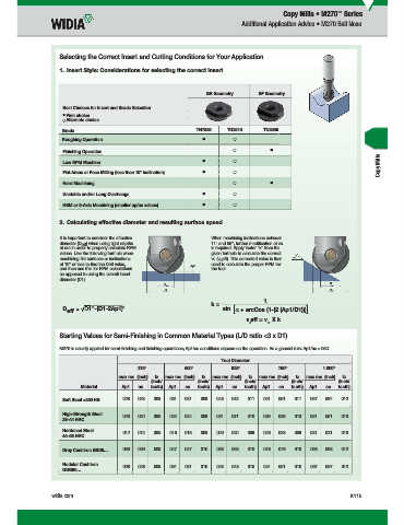
                      Selecting the Correct Insert and Cutting Conditions for Your Application
                      1.  Insert Style: Considerations for selecting the correct insert


                                                                   BR Geometry      BF Geometry

                     Best Choices for Insert and Grade Selection
                       First choice

                       Alternate choice

                     Grade                                      TN7535    TN2510      TN2505
                     Roughing Operation
                     Finishing Operation
                                                                                                                            Copy Mills
                     Low RPM Machine
                     Flat Areas or Face Milling (less than 10° inclination)
                     Hard Machining
                     Unstable and/or Long Overhangs
                     HSM or 5-Axis Machining (smaller ap/ae values)


                      2.  Calculating effective diameter and resulting surface speed

                      It is important to consider the effective        When machining inclinations between
                    diameter (D eff ) when using light depths        11° and 55°, further modifi cation of vc
                    of cut in order to properly calculate RPM        is required. Apply factor “k” from the
                    values. Use the following formula when           given formula to calculate the correct
                    machining fl at surfaces or inclinations         vc (v eff). This corrected value is then   α
                                                                        c
                    of 10° or less to fi nd the Deff value,          used to calculate the proper RPM for
                                                               Ap1
                    and then use this for RPM calculations           the tool.
                    as opposed to using the overall insert
                    diameter (D1).
                                                      D eff                                                D eff
                                                      D 1                                                  D 1
                                                                                      1
                                                                     k =
                        D eff   2 -(D1-2Ap1) 2                           sin [α + arcCos (1-(2 (Ap1/D1)))]
                                                                                v eff = v  X k
                                                                                 c     c
                      Starting Values for Semi-Finishing in Common Material Types (L/D ratio <3 x D1)

                      M270 is usually applied for semi-fi nishing and fi nishing operations; Ap1/ae conditions depend on the operation. As a general rule: Ap1/ae ).05D.
                                                                        Tool Diameter
                                             .375"          .500"          .625"          .750"          1.000"
                                       max rec. (inch)  fz   max rec. (inch)  fz   max rec. (inch)  fz   max rec. (inch)  fz   max rec. (inch)  fz
                                                  (inch/         (inch/         (inch/         (inch/         (inch/
                           Material     Ap1   ae  tooth)  Ap1  ae  tooth)  Ap1  ae  tooth)  Ap1  ae  tooth)  Ap1  ae  tooth)
                     Soft Steel <250 HB  .028  .028  .008  .031  .031  .008  .043  .043  .011  .051  .051  .011  .067  .067  .012

                     High-Strength Steel    .020  .020  .006  .024  .024  .008  .031  .031  .010  .039  .039  .010  .051  .051  .010
                     33–44 HRC

                     Hardened Steel     .012  .012  .006  .016  .016  .008  .020  .020  .009  .028  .028  .009  .031  .031  .010
                     44–55 HRC

                     Gray Cast Iron GG25…  .039  .039  .008  .047  .047  .010  .063  .063  .010  .078  .078  .010  .098  .098  .012
                     Nodular Cast Iron   .028  .028  .008  .031  .031  .010  .043  .043  .010  .051  .051  .010  .067  .067  .012
                     GGG60…


                  widia.com                                                                                       K115


         WID_Master16_IndexableMIlling_CopyMills_K114_K115_Minch_REBRAND.indd   115  L  V i WID M  16 I d  bl MIlli  C  Mill K114 K115 Mi h REBRANDO b 1420151153AM
                                                                                                                   10/29/15   1:44 PM
   1018   1019   1020   1021   1022   1023   1024   1025   1026   1027   1028