


Page 44 - Handout Computer Network.
P. 44
https://www.youtube.com/watch?v=mpFWIZ318eQ


                     2.10.1.1  Bus Topology


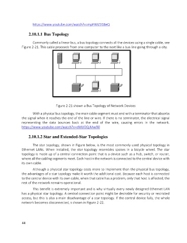
                      Commonly called a linear bus, a bus topology connects all the devices using a single cable, see
               Figure 2-21. This cable proceeds from one computer to the next like a bus line going through a city.


                                      Figure 2-21 shown a Bus Topology of Network Devices


                      With a physical bus topology, the main cable segment must end with a terminator that absorbs
               the signal when it reaches the end of the line or wire. If there is no terminator, the electrical signal
               representing  the  data  bounces  back  at  the  end  of  the  wire,  causing  errors  in  the  network.
               https://www.youtube.com/watch?v=dMUOQj4AwB0


                    2.10.1.2 Star and Extended-Star Topologies

                      The star topology, shown in Figure below, is the most commonly used physical topology in
               Ethernet  LANs.  When  installed,  the  star  topology  resembles  spokes  in  a  bicycle  wheel.  The  star
               topology is made up of a central connection point that is a device such as a hub, switch, or router,
               where all the cabling segments meet. Each host in the network is connected to the central device with
               its own cable.
                      Although a physical star topology costs more to implement than the physical bus topology,
               the advantages of a star topology make it worth the additional cost. Because each host is connected
               to the central device with its own cable, when that cable has a problem, only that host is affected; the
               rest of the network remains operational.
                      This benefit is extremely important and is why virtually every newly designed Ethernet LAN
               has a physical star topology. A central connection point might be desirable for security or restricted
               access, but this is also a main disadvantage of a star topology. If the central device fails, the whole
               network becomes disconnected, s shown in Figure 2-22.


               44

