


Page 41 - Handout Computer Network.
P. 41
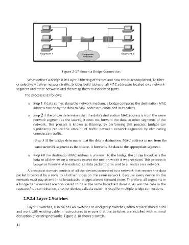
Figure 2-17 shown a Bridge Connection


                   What defines a bridge is its Layer 2 filtering of frames and how this is accomplished. To filter
            or selectively deliver network traffic, bridges build tables of all MAC addresses located on a network
            segment and other networks and then map them to associated ports.

                      The process is as follows:

                   o  Step 1 If data comes along the network medium, a bridge compares the destination MAC
                       address carried by the data to MAC addresses contained in its tables.

                   o  Step 2 If the bridge determines that the data’s destination MAC address is from the same
                       network segment as the source, it does not forward the data to other segments of the
                       network.  This  process  is  known  as  filtering.  By  performing  this  process,  bridges  can
                       significantly  reduce  the  amount  of  traffic  between  network  segments  by  eliminating
                       unnecessary traffic.

                       Step 3 If the bridge determines that the data’s destination MAC address is not from the
                        same network segment as the source, it forwards the data to the appropriate segment.


                   o  Step 4 If the destination MAC address is unknown to the bridge, the bridge broadcasts the
                       data to all devices on a network except the one on which it was received. This process is
                       known as flooding. A broadcast is a data packet that is sent to all nodes on a network.
                   A broadcast domain consists of all the devices connected to a network that receive the data
            packet broadcast by a node to all other nodes on the same network. Because every device on the
            network must pay attention to broadcasts, bridges always forward them. Therefore, all segments in
            a bridged environment are considered to be in the same broadcast domain. As was the case in the
            repeater/hub combination, another device, called a switch, is used for multiple bridge connections.

                 2.9.2.4 Layer 2 Switches


                   Layer 2 switches, also called LAN switches or workgroup switches, often replace shared hubs
            and work with existing cable infrastructures to ensure that the switches are installed with minimal
            disruption of existing networks. Figure 2-18 shows a switch.

            41

