


Page 57 - M. Abrahim Thesis
P. 57
Computer Network                                                             2021


                       •  Media and connector size—Small

                       •  Maximum cable length—100 m (short)

                    Commonly used types of UTP cabling are as follows:

                       •  Category  1  (CAT  1)—Used  for  telephone  communications.  Not  suitable  for
                           transmitting data.

                       •  Category 2 (CAT 2)—Capable of transmitting data at speeds up to 4 Mbps.

                       •  Category 3 (CAT 3)—Used in 10BASET Ethernet networks. Can transmit data at
                           speeds up to 10 Mbps.
                       •  Category 4 (CAT 4)—Used in Token Ring networks. Can transmit data at speeds
                           up to 16 Mbps.

                       •  Category 5 (CAT 5)—Can transmit data at speeds up to 100 Mbps. Used in Fast
                           Ethernet networks.
                       •  Category 5e (CAT 5e)—Used in networks running at speeds up to 1000 Mbps (1
                           Gbps). Used in Gigabit Ethernet (GigE) networks.

                       •  Category 6 (CAT 6)—The specification for CAT 6 is new, was released on February
                           3,  2003,  and  is  currently  available  for  installation  and  use.  Used  in  Gigabit
                           Ethernet (GigE) networks.
                       •  https://www.youtube.com/watch?v=fgOkvIHKgXQ

            3.3   Optical Media

                   Optical fiber is the most frequently used medium for the longer, high bandwidth, pointto-
            point transmissions required on LAN backbones and on wide-area networks (WANs).
                   Total Internal Reflection A light ray that is being turned on and off to send data 1s and 0s
            into an optical fiber must stay inside the fiber until it reaches the far end. The ray must not
            refract into the material wrapped around the outside of the fiber because such refraction causes
            the loss of part of the ray’s light energy. A design for the fiber that makes the outside surface of
            the fiber act like a mirror to the light ray moving through the fiber must be achieved. If any light
            ray that tries to move out through the side of the fiber is reflected back into the fiber at an angle
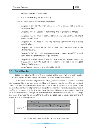
            that sends it towards the far end of the fiber, this is a good pipe or wave guide for the light
            waves, as illustrated in Figure 3-4.


                             Figure 3-4 shown a wave guide for the light waves Structure


                                                         67

