
Page 30 - StanochnyPark
P. 30
PROFESSIONAL ADVICE PROFESSIONAL ADVICE
The Taylor model
Mathematical models effectively calculate tool factors relevant to metal cutting. Taylor observed that increasing depth of cut had minimal effect on
In the early 1900s American engineer FW Taylor developed a tool life model that included
life In a metal cutting operation, a tool deforms workpiece abrasive wear tool life. Increasing feed rate had somewhat more
effect, while higher cutting speeds influenced tool
material and causes it to shear away in the form of chips. The life the most. This prompted Taylor to develop a
deformation process requires a significant amount of force, and model focused on the effect of varying cutting
the tool endures a variety of mechanical, thermal, chemical and tribological loads. Over a period speeds. The equation for Taylor’s basic model is
of time, these loads eventually cause the tool to wear to the point that it must be replaced. vC * Tm = CT, where vC is cutting speed, T is
Accurately predicting tool life allows you to plan your metalworking processes based on flank wear tool life, and m and CT are constants with CT
tool wear, control costs, and avoid unplanned downtime due to unpredictable tool behavior or representing the cutting speed that would result
unacceptable machining quality. in a tool life of one minute.
Taylor also observed that tool wear
typically accelerates at the beginning of an
Accordingly, for more than a century, scientists and time operation, settles into a steady but slower rise
engineers have created and tested mathematical models in a second phase, and finally enters a third and
that factor in the forces upon a tool to provide estimates of final phase of rapid wear until the end of tool life.
expected tool life. Many of these models focus on a specific He designed his model to represent the length of
tool’s performance in a certain material and operation, time between phases two and three.
and simple formulas and repetitive testing produce valid As a result, Taylor’s model does not apply at lower cutting speeds in which workpiece
tool wear projections. However, generalised models that material adheres to and builds up on the cutting edge, affecting the quality of the cut and
can be applied across a wide range of workpiece materials damaging the tool. Also outside the model’s scope are cutting speeds high enough to promote
and tools are more useful in industrial applications. chemical wear. The low- and high-speed wear modes share the characteristics of unpredictability
Because these models take into account a variety of tool – wear resulting from adhesive or chemical mechanisms can occur either quickly or slowly. The
wear factors, their mathematical complexity increases in Taylor model is based on the second phase of tool life, namely steady and predictable abrasive
accordance with the number of factors considered – the wear.
more factors, the more complex the calculation. The original Taylor model concentrates on the effects of cutting speed and is valid if depth
While simple tool life equations can be solved via handwritten mathematics and manual of cut and feed do not change. After depth of cut and feed are established, speed is manipulated
calculation, today’s computer-executed analysis is necessary to solve equations of complex to modify tool life.
models in an amount of time that is practical within a production environment. Digital calculations Further experiments led to development of an extended Taylor tool life model equation
are very reliable, but manufacturers should maintain a critical attitude towards the results, that included more variables and consequently was more complex. The equation also includes a
especially when machining advanced workpiece materials and employing extreme machining variable that accounts for the rake angle of the tool, as well as constants for various workpiece
parameters. Overall, progress in tool life model development has brought academic theory and materials. Despite the additional factors, this model is most accurate when changing one cutting
practical application into close alignment. condition at a time. Altering several conditions simultaneously can produce inconsistent results.
The Archard model Also, the original Taylor model was unable to fully account for the geometric relationship
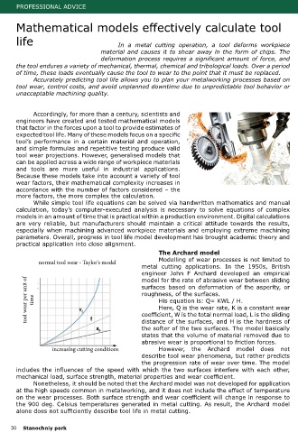
Modelling of wear processes is not limited to of the cutting tool to the workpiece. A cutting edge can be engaged in a workpiece in an
normal tool wear - Taylor's model
metal cutting applications. In the 1950s, British orthogonal orientation (perpendicular to the
engineer John F Archard developed an empirical direction of feed), or obliquely (at a rake angle
relative to the feed direction). And, a cutting
tool wear per unit of time surfaces based on deformation of the asperity, or not involved in cutting and "non-free" when
model for the rate of abrasive wear between sliding
edge is considered "free" if its corners are
roughness, of the surfaces.
the tool’s corner is engaged in the workpiece.
His equation is: Q= KWL / H.
Free orthogonal or free oblique cuts are
Here, Q is the wear rate, K is a constant wear
rarely present in modern metal cutting, so
coefficient, W is the total normal load, L is the sliding
distance of the surfaces, and H is the hardness of
equation added a variable for cutting edge
the softer of the two surfaces. The model basically their relevance is limited. Taylor’s extended
states that the volume of material removed due to rake angle, but no allowance was made for
abrasive wear is proportional to friction forces. corner engagement of the tool.
increasing cutting conditions However, the Archard model does not The Taylor model has shortcomings when viewed in hindsight from today’s level of metal
describe tool wear phenomena, but rather predicts cutting technology and complexity. However, over its long history the Taylor model has been an
the progression rate of wear over time. The model excellent basis for tool life predictions and under certain conditions still provides valid tool life
includes the influences of the speed with which the two surfaces interfere with each other, data.
mechanical load, surface strength, material properties and wear coefficient. Role of chip thickness
Nonetheless, it should be noted that the Archard model was not developed for application As engineers developed and studied tool life models, it became clear that the generated
at the high speeds common in metalworking, and it does not include the effect of temperature chip thickness is closely related to tool life. Chip thickness is a function of depth of cut and feed
on the wear processes. Both surface strength and wear coefficient will change in response to measured perpendicular to the cutting edge and in the plane perpendicular to the direction of
the 900 deg. Celsius temperatures generated in metal cutting. As result, the Archard model cutting. If the cutting edge angle is 90 degrees (0 degrees lead angle in the US), depth of cut
alone does not sufficiently describe tool life in metal cutting. and chip width are the same, and feed and chip thickness are as well.
The extent that the tool’s corner is engaged in the workpiece adds another variable to
30 Stanochniy park Stanochniy park 31