
Page 8 - 2020 7th St Presentation
P. 8
CANAL
L:\21-133 Toscana 2020 7th St S\ALD-Dwgs\21-133.dwg, 9/12/2021 10:27:25 PM, AutoCAD PDF (General Documentation).pc3
Index
LINE AT THE FACE OF SEAWALL
BOUNDARY AND MEAN HIGH
A 1.7 A CONCRETE DRIVEWAY 2150 Sf
L:\21-133 Toscana 2020 7th St S\ALD-Dwgs\21-133.dwg, Plotted on 9/12/2021 10:27:26 PM by Christian Andrea
B POOL 946 Sf
B1. Glass Tile Water Line
E C3
B2. Pearl Finish
B3. Spa 52 Sf
G LANDSCAPE ARCHITECTURE
B4. Chaise Shelf 126 Sf
2780 S. Horseshoe Drive Suite 5
(2)2" (1)6" Sleeves
B5. Pool Equipment Gas Heater Naples, FL 34104
9'
B B7 B4
L1
B6. Shellstone Coping 1.5" think min sq edge (239) 430-1661
SEAWALL CAP
D
I B7. Vanishing Edge Design@ALDinc.net
PLATTED LOT LINE
1.2' WIDE CONCRETE
License LC26000259
VANISHING EDGE
D C PATIO
C PILE (TYPICAL) Christian Andrea
1.7 WOOD MOORING C1. Pool Deck Shellstone Paving 12x24 mudset 2273 Sf
C2. Patio & Walkway Shellstone 12x24 16 Sf
CHAISE SHELF WOOD DOCK
POOL DECK C3. Wood Deck 313 Sf
(6" water depth)
C1 G
J D RETAINING WALL (Concrete Block) License No. 1178
25' Rear Setback WOOD DOCK
15' Pool Setback
F2 E FIRE TABLE Copyright Architectural Land Design ©
POOL
B F FENCE
1.7 F1. Gate (Self Latching)
D
F2. 4' Fence (Bronze)
B3 C1
OUTDOOR LIVING
G STEPS Treads and risers to match pool coping
SPA POOL DECK
L CANAL
H STEP STONES
WIDTH VARIES
(2)2" (1)6" Sleeves
I WOOD DOCK
13' L
(PLAT BOOK 3, PAGE 2)
J WATER MANAGEMENT BERM
B5
7'-6" Side Setback
K DRAIN SYSTEM
L GUTTER
BLOCK 13
JANDY 3-WAY JANDY 3-WAY NEVER LUBE
NEVER LUBE
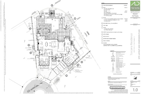
VERIFY MATERIALS WITH OWNER. Toscana Residence 2020 7th St. S. City of Naples, FL SITE LAYOUT AND DIMENSION PLAN
N00°58'30"E 99.43' (P)
D2
N00°58'30"E 99.67' (M)
1.5 CONTRACTOR TO CONFIRM ALL QUANTITIES.
authorization. Any deviations or inaccuracies need to be brought to the attention of the Owner immediately. * All base information has been provided by others, verification of setbacks, property lines, etc. need to be provided by others. * It is the Contractors responsibility to verify that he has the most current plan. * Contractor shall not scale from plan, use dimensions only. * These plans are the property of Architectural Land Design and may not be used or reproduced without This Document contains information proprietory to ARCHITECTURAL LAND DESIGN and no part of this drawing shall be reproduced or disclosed to others or used for any purpose other than that for which it was furnished, without prior written permission from ARCHITECTURAL LAND DESIGN. (Aluminum, Color TBD by Owner) BEARING BASIS S26°36'30"W 154.42' (M) (IMPROVEMENTS NOT LOCATED) WITH DAVIT
4' Tall Fence
3' Wide Gate LOT 9 CONCRETE PAD
(Aluminum, Self-Latching)
Legend:
Legend:
S26°36'30"W 150.74' (P)
F1
D1 G 100'-0" Depicts Proposed Grade Information
1.5 (Reflects Finished Grade)
100.0' Depicts Existing Grade Information
D
C1 Direction of Drainage Flow
F2
Sleeves, Sch. 40 PVC (see plans)
4' Tall Fence
4" Drain Pipe
(Aluminum, Color TBD by Owner)
Stepping Stone
(PVC or Smooth Walled Corrugated)
(3.5' x 3.5' x 3" Thick - Cast Stone)
LOT 10
ENTRY 6" Drain Pipe
H J (PVC or Smooth Walled Corrugated)
C
10'-6" D2 (PVC or Smooth Walled Corrugated)
1.4 8" Drain Pipe
1.5 Catch Basin w/ Atrium grate
12' AD (See Detail 'A' on Details Sheet)
CB10 10" Round Grate Connected to 8" Pipe
(2)2" (1)6" Sleeves 7'-6" Side Setback (See Detail 'B' on Details Sheet)
D1
13' 19' 8" Round Grate Connected to 6" Pipe
1.5 CB8 (See Detail 'B' on Details Sheet)
(2)2" (1)6" Sleeves
MOTOR COURT Downspout Connected to Gutter
F1 3' Wide Gate DS
21'-4" 18' (Aluminum, Self-Latching) (See Detail 'C' on Details Sheet)
CB9 9" Catch Basin
21'-11 1 " 8 L 8'-8" 12' DRIVE 7'-4 8 " S80°24'06"W 123.06' (M) S80°20'30"W 122.97' (P) Stepping Stone CB12 12" Catch Basin
1
18" Catch Basin
CB18
10'-6" (3.5' x 4'-4" x 3" Thick - Cast Stone) 1' Proposed Contour Line Drawing Date: IS 07.09.21
0'
(7) Stepping Stones
30' Front Setback H Contractor to verify all quantities. Scale: 1" = 10'-0"
(3' x 3' x 3" Thick - Cast Stone)
Existing Contour Line
3
7'-5 " A B 21-133
4
1.4
Notes
20' 10'-3 4 "
3
LOT 8
Confirm selections with owner before ordering.
Contractor to confirm quantities.
BRICK
DRIVE
File Name: 21-133.dwg
Sleeving
1'-8"
All planter areas are to receive sleeves for irrigation and landscape lighting. Architectural Information Provided By:
Sleeve sizes are to be 2 sizes larger than actual pipe size. Company Name: ----
File Name: ----
BRICK
Date: ----
24'
Average Crown of Road: 1'-8" Landscape Lighting Site Information Provided By:
(3.2'+3.1') / 2=3.15' Company Name: ----
File Name: ----
It is anticipated that Landscape lighting will be installed. Date: ----
4'-9"
All grades Represent Finished Grades
BLOCK 13
Unless Otherwise Noted (ie. 'Slab')
1.0
PAVED
Contractor to verify property lines and setbacks before construction.
Contractor must have property lines staked and located,
and must verify plan dimensions and field conditions are consistent.
Any Inconsistencies w/ these plans need to be reported to ALD and the Owner.
7TH STREET SOUTH
(NAVD 1988)
Contractor shall verify that he has the most up to date plans, and that they have
ELEV. = 3.90'
Contractor shall verify that he has the most up to date plans, and that they have been approved and accepted by the Owner before commencing construction. been approved and accepted by the Owner before commencing construction.
BENCHMARK