
Page 9 - 2020 7th St Presentation
P. 9
CANAL
L:\21-133 Toscana 2020 7th St S\ALD-Dwgs\21-133.dwg, 9/12/2021 10:27:27 PM, AutoCAD PDF (General Documentation).pc3
L:\21-133 Toscana 2020 7th St S\ALD-Dwgs\21-133.dwg, Plotted on 9/12/2021 10:27:29 PM by Christian Andrea
2.1' BOUNDARY AND MEAN HIGH LINE AT THE FACE OF SEAWALL
LANDSCAPE ARCHITECTURE
2.1
3'-0" 2.6 (2)2" (1)6" Sleeves 2780 S. Horseshoe Drive Suite 5
9' Naples, FL 34104
L1
2.1' 2.3 7'-6" 7'-6" (239) 430-1661
SEAWALL CAP
4'-6" AD AD Design@ALDinc.net
PLATTED LOT LINE
1.2' WIDE CONCRETE
6'-0" AD 5'-6" 3'-6" 5'-6" 6'-0" License LC26000259
2.1
AD AD
CB VANISHING EDGE CB 2.3'
7'-6" 2.3 PILE (TYPICAL) WOOD MOORING Christian Andrea
2.0
CHAISE SHELF 2.5 WOOD DOCK
POOL DECK
3.4
(6" water depth)
2.7
7'-6" 4.1 7'-6" 7'-6" 3'-0" License No. 1178
CB Copyright Architectural Land Design ©
6'-0"
15' Pool Setback
4'-6"
POOL 4.4 25' Rear Setback WOOD DOCK
3.5
7'-5" AD AD 6'-0" 2.5 CB
AD
6'-0" AD 6'-0" AD
CB 7'-6" 3.5
OUTDOOR LIVING 5.3 4.5
7'-7" 4.6
3.5
3.0
4.6
SPA POOL DECK
CB DS 4.3 2.3 CANAL
7'-6" 7'-6"
7'-8" (PLAT BOOK 3, PAGE 2)
(2)2" (1)6" Sleeves 3.3
WIDTH VARIES
4.2 AD 13' AD 6'-0" 4.4 CB
7'-8"
CB DS 4.6
7'-6" Side Setback
4.1' 3.3 2.8'
8'-0" 2.8 N00°58'30"E 99.67' (M)
4.1
BLOCK 13
4.2
NEVER LUBE JANDY 3-WAY JANDY 3-WAY NEVER LUBE
3.9
4.2
N00°58'30"E 99.43' (P)
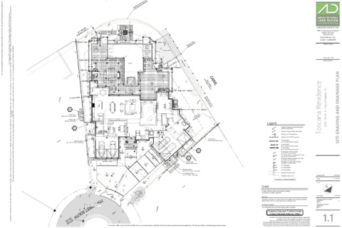
D2 Toscana Residence 2020 7th St. S. City of Naples, FL SITE GRADING AND DRAINAGE PLAN
1.5 DS 3.8 CB
authorization. Any deviations or inaccuracies need to be brought to the attention of the Owner immediately. * All base information has been provided by others, verification of setbacks, property lines, etc. need to be provided by others. * It is the Contractors responsibility to verify that he has the most current plan. * Contractor shall not scale from plan, use dimensions only. * These plans are the property of Architectural Land Design and may not be used or reproduced without This Document contains information proprietory to ARCHITECTURAL LAND DESIGN and no part of this drawing shall be reproduced or disclosed to others or used for any purpose other than that for which it was furnished, without prior written permission from ARCHITECTURAL LAND DESIGN. (Aluminum, Color TBD by Owner) BEARING BASIS S26°36'30"W 154.42' (M) (IMPROVEMENTS NOT LOCATED) 3.4 WITH DAVIT
4' Tall Fence
3' Wide Gate LOT 9 5.5 CONCRETE PAD
(Aluminum, Self-Latching)
Legend:
CB DS
Legend:
S26°36'30"W 150.74' (P)
2.0
D1 5.4 4.7 2.2 100'-0" Depicts Proposed Grade Information
1.5 (Reflects Finished Grade)
4'-2" 4.4 7'-8" 4.2 7'-8" 100.0' Depicts Existing Grade Information
4.3
Direction of Drainage Flow
6'-2" 7'-8" 6'-2"
4.5
5'-8" DS 3.7 Sleeves, Sch. 40 PVC (see plans)
4' Tall Fence
4" Drain Pipe
(Aluminum, Color TBD by Owner)
DS
Stepping Stone
(PVC or Smooth Walled Corrugated)
(3.5' x 3.5' x 3" Thick - Cast Stone) DS CB
LOT 10
7'-7" 6" Drain Pipe
ENTRY
(PVC or Smooth Walled Corrugated)
4.6
8" Drain Pipe
6'-1" 4.6 D2 (PVC or Smooth Walled Corrugated)
4.2
6'-0" 4.6 1.5 AD Catch Basin w/ Atrium grate
4'-2" 3.8' (See Detail 'A' on Details Sheet)
4.0
5.1
5.0
6'-0" (2)2" (1)6" Sleeves 5.7 (2)2" (1)6" Sleeves 3.8 7'-6" Side Setback CB10 10" Round Grate Connected to 8" Pipe
(See Detail 'B' on Details Sheet)
D1
CB DS 4.6 DS 13' 19' 5'-8" 1.5 8" Round Grate Connected to 6" Pipe
CB CB8 (See Detail 'B' on Details Sheet)
MOTOR COURT 3' Wide Gate Downspout Connected to Gutter
4.0' (Aluminum, Self-Latching) DS (See Detail 'C' on Details Sheet)
DS
3.9
CB9 9" Catch Basin
4.0
4.1
CB
5.7
3.8
CB12 12" Catch Basin
CB
DRIVE S80°20'30"W 122.97' (P) Stepping Stone CB18 18" Catch Basin
(3.5' x 4'-4" x 3" Thick - Cast Stone)
0' Proposed Contour Line
5'-0" 4.3' (7) Stepping Stones 1' Existing Contour Line Drawing Date: IS 07.09.21
S80°24'06"W 123.06' (M)
30' Front Setback 4.2 4.4 4.3 Contractor to verify all quantities. 21-133 1" = 10'-0"
(3' x 3' x 3" Thick - Cast Stone)
4.2
3.5
Scale:
3.9
3.6
4.1
3.4
3.2' 3.3 3.3 3.6 4.0 LOT 8 Notes
3.2
Confirm selections with owner before ordering.
4.2
3.4
Contractor to confirm quantities.
BRICK
2.9
3.5
DRIVE
3.0
3.3
File Name: 21-133.dwg
2.8
Sleeving
3.0
2.9
2.9
3.1
All planter areas are to receive sleeves for irrigation and landscape lighting. Architectural Information Provided By:
2.8
Sleeve sizes are to be 2 sizes larger than actual pipe size. Company Name: ----
3.1
2.8' File Name: ----
BRICK
Date:
----
Average Crown of Road: 3.6 Landscape Lighting Site Information Provided By:
(3.2'+3.1') / 2=3.15' 2.8 Company Name: ----
File Name: ----
It is anticipated that Landscape lighting will be installed. Date: ----
All grades Represent Finished Grades
3.2
BLOCK 13
Unless Otherwise Noted (ie. 'Slab')
2.8
1.1
PAVED
3.4
Contractor to verify property lines and setbacks before construction.
3.3
Contractor must have property lines staked and located,
and must verify plan dimensions and field conditions are consistent.
Any Inconsistencies w/ these plans need to be reported to ALD and the Owner.
7TH STREET SOUTH
(NAVD 1988)
3.1
Contractor shall verify that he has the most up to date plans, and that they have
ELEV. = 3.90'
Contractor shall verify that he has the most up to date plans, and that they have been approved and accepted by the Owner before commencing construction. been approved and accepted by the Owner before commencing construction.
BENCHMARK