
Page 395 - Kitab3DsMax
P. 395
Chapter 12: Drawing and Editing 2D Splines and Shapes
Bevel and Bevel Profile modifiers
Another common set of modifiers that can be used with splines and shapes are the Bevel and Bevel Profile
modifiers.
Note
Both the Bevel and Bevel Profile modifiers are not found in the Modifiers menu. To apply them, use the Modifier
List found in the Modifier Stack. They are among the Object-Space modifiers. n
Using the Bevel modifier, you can extrude and outline (scale) the shape in one operation. With the Bevel
modifier, you can set the Height and Outline values for up to three different bevel levels. The Capping
options let you select to cap either end of the beveled shape. The Cap Type can be either Morph or Grid.
The Morph type is for objects that will be morphed. You can specify that the Surface use Linear or Curved
Sides with a given number of segments. You can also select to Smooth Across Levels automatically. The
Keep Lines from Crossing option avoids problems that may result from crossing lines.
The Bevel Profile modifier lets you select a spline to use for the bevel profile.
Tutorial: Modeling unique rings
You can create a simple ring using a Tube or Torus primitive object (or with an extruded donut shape), but
if you want the ring to have a unique profile, then the Bevel and Bevel Profile modifiers are what you need.
To create a couple of unique rings with the Bevel and Bevel Profile modifiers, follow these steps:
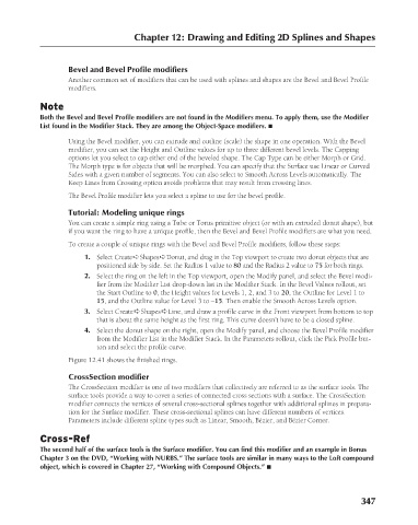
1. Select Create ➪ Shapes ➪ Donut, and drag in the Top viewport to create two donut objects that are
positioned side by side. Set the Radius 1 value to 80 and the Radius 2 value to 75 for both rings.
2. Select the ring on the left in the Top viewport, open the Modify panel, and select the Bevel modi-
fier from the Modifier List drop-down list in the Modifier Stack. In the Bevel Values rollout, set
the Start Outline to 0, the Height values for Levels 1, 2, and 3 to 20, the Outline for Level 1 to
15, and the Outline value for Level 3 to –15. Then enable the Smooth Across Levels option.
3. Select Create ➪ Shapes ➪ Line, and draw a profile curve in the Front viewport from bottom to top
that is about the same height as the first ring. This curve doesn’t have to be a closed spline.
4. Select the donut shape on the right, open the Modify panel, and choose the Bevel Profile modifier
from the Modifier List in the Modifier Stack. In the Parameters rollout, click the Pick Profile but-
ton and select the profile curve.
Figure 12.41 shows the finished rings.
CrossSection modifier
The CrossSection modifier is one of two modifiers that collectively are referred to as the surface tools. The
surface tools provide a way to cover a series of connected cross sections with a surface. The CrossSection
modifier connects the vertices of several cross-sectional splines together with additional splines in prepara-
tion for the Surface modifier. These cross-sectional splines can have different numbers of vertices.
Parameters include different spline types such as Linear, Smooth, Bézier, and Bézier Corner.
Cross-Ref
The second half of the surface tools is the Surface modifier. You can find this modifier and an example in Bonus
Chapter 3 on the DVD, “Working with NURBS.” The surface tools are similar in many ways to the Loft compound
object, which is covered in Chapter 27, “Working with Compound Objects.” n
347
6/30/10 4:20 PM
19_617779-ch12.indd 347
19_617779-ch12.indd 347 6/30/10 4:20 PM