
Page 461 - Kitab3DsMax
P. 461
Chapter 14: Using the Graphite Modeling Tools and Painting with Objects
The Edge method splits each edge at its midpoint. For example, a triangular face would be split into three
smaller triangles. The Tension spinner to the right of the Tessellate button specifies a value that is used to
make the tessellated face concave or convex.
The Face option creates a vertex in the center of the face and also creates three new edges, which extend
from the center vertex to each original vertex. For a square polygon, this option would create six new trian-
gular faces. (Remember, a square polygon is actually composed of two triangular faces.)
Use Displacement
The Use Displacement tool opens the Subdivision panel, shown in Figure 14.14, when enabled. Using this
panel, you can specify the subdivision method that is used and the settings for the displacement.
Cross-Ref
You can learn more about using displacement maps in Chapter 18, “Creating Compound Materials and Using
Material Modifiers.” n
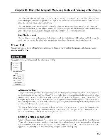
FIGURE 13.14
The Subdivision panel includes all the subdivision settings.
Alignment options
A single vertex or two vertices don’t define a plane, but three or more vertices do. If three or more vertices
are selected, you can use the Make Planar button to make these vertices coplanar (which means that all ver-
tices are on the same plane). Doing so positions the selected vertices so that they lie in the same plane. This
is helpful if you want to build a new polygon face. Polygonal faces need to be coplanar. This button works
in all subobject modes. The X, Y, and Z buttons let you collapse the current object or subobject selection to
a single plane lying on the specified axis.
The View and Grid Align buttons move and orient all selected vertices to the current active viewport or to
the current construction grid. These buttons can also be used in all subobject modes. This causes all the
selected face normals to point directly at the grid or view.
Editing Vertex subobjects
When working with the Editable Poly objects, after you select a Vertex subobject mode (keyboard shortcut,
1) and select vertices, you can transform them using the transform buttons on the main toolbar. All vertex-
specific commands are found within the Vertices panel, shown in Figure 14.15, but some new tools also
appear in the Geometry (All) panel including Collapse, Detach, and Cap Poly.
413
6/30/10 4:23 PM
21_617779-ch14.indd 413 6/30/10 4:23 PM
21_617779-ch14.indd 413