
Page 981 - Kitab3DsMax
P. 981
Chapter 38: Working with Inverse Kinematics
the base cylinder, and the bucket to the arm to the housing. The connections should look like
those in Figure 38.2.
Cross-Ref
You can learn more about the Schematic View window in Chapter 25, “Working with the Schematic View.” n
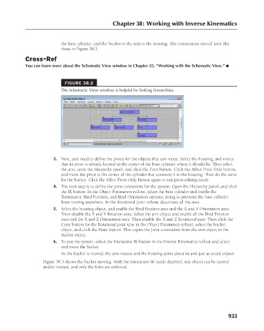
FIGURE 38.2
The Schematic View window is helpful for linking hierarchies.
3. Next, you need to define the pivots for the objects that can rotate. Select the housing, and notice
that its pivot is already located in the center of the base cylinder where it should be. Then select
the arm, open the Hierarchy panel, and click the Pivot button. Click the Affect Pivot Only button,
and move the pivot to the center of the cylinder that connects it to the housing. Then do the same
for the bucket. Click the Affect Pivot Only button again to exit pivot-editing mode.
4. The next step is to define the joint constraints for the system. Open the Hierarchy panel, and click
the IK button. In the Object Parameters rollout, select the base cylinder and enable the
Terminator, Bind Position, and Bind Orientation options; doing so prevents the base cylinder
from moving anywhere. In the Rotational Joint rollout, deactivate all the axes.
5. Select the housing object, and enable the Bind Position axes and the X and Y Orientation axes.
Then disable the X and Y Rotation axes. Select the arm object and enable all the Bind Position
axes and the X and Z Orientation axes. Then disable the X and Z Rotational axes. Then click the
Copy button for the Rotational joint type in the Object Parameters rollout, select the bucket
object, and click the Paste button. This copies the joint constraints from the arm object to the
bucket object.
6. To test the system, select the Interactive IK button in the Inverse Kinematics rollout and select
and move the bucket.
As the bucket is moved, the arm rotates and the housing spins about its axis just as you’d expect.
Figure 38.3 shows the bucket moving. With the Interactive IK mode disabled, any object can be moved
and/or rotated, and only the links are enforced.
933