
Page 979 - Kitab3DsMax
P. 979
Chapter 38: Working with Inverse Kinematics
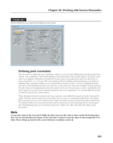
FIGURE 38.1
The IK rollouts let you control the binding of an IK system.
Defining joint constraints
The next step is to define the joint constraints, which you specify in the Sliding Joints and Rotational Joints
rollouts. The availability of these limits depends on the selected IK Solver and its options. By default, each
joint has six degrees of freedom, meaning that the two objects that make up the joint can each move or
rotate along the X-, Y-, or Z-axes. The axis settings for all other sliding and rotational joints are identical.
Defining joint constraints enables you to constrain these motions in order to prevent unnatural motions,
such as an elbow bending backward. To constrain an axis, select the object that includes the pivot point for
the joint, locate in the appropriate rollout the section for the axis that you want to restrict, and deselect the
Active option. If an axis’s Active option is deselected, the axis is constrained. You can also limit the motion
of joints by selecting the Limited option.
When the Limited option is selected, the object can move only within the bounds set by the From and To
values. The Ease option causes the motion of the object to slow as it approaches either limit. The Spring
Back option lets you set a rest position for the object; the object returns to this position when pulled away.
The Spring Tension sets the amount of force that the object uses to resist being moved from its rest posi-
tion. The Damping value sets the friction in the joint, which is the value with which the object resists
any motion.
Note
As you enter values in the From and To fields, the object moves to that value to show visually the location speci-
fied. You can also hold down the mouse on the From and To values to cause the object to move temporally to its
limits. These settings are based on the current Reference Coordinate system. n
931