
Page 987 - Kitab3DsMax
P. 987
Chapter 38: Working with Inverse Kinematics
Defining a swivel angle
The IK Solver Properties rollout includes the Swivel Angle value. The swivel angle defines the plane that
includes the joint objects and the line that connects the starting and ending joints. This plane is key because
it defines the direction that the joint moves when bent.
The Swivel Angle value can change during an animation. Using the Pick Target button, you can also select
a Target object to control the swivel angle. The Use button turns the target on and off. The Parent Space
group defines whether the IK Goal’s parent object or the Start Joint’s parent object is used to define the
plane. Having an option lets you select two different parent objects that control the swivel plane if two or
more IK solvers are applied to a single IK chain.
You can also change the Swivel Angle value by using a manipulator. To view the manipulator, click the
Select and Manipulate button on the main toolbar. This manipulator is a green line with a square on the
end of it. Dragging this manipulator in the viewports causes the swivel angle to change.
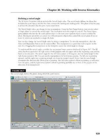
To understand the swivel angle, consider the two puppet bones systems displayed in Figure 38.7. The HI
solver has been applied to the right arms of both puppets with the upper arm as the beginning joint and the
hand as the end joint. The swivel angle for the left bones system is 90 degrees, and the swivel angle for the
right bones system is 180. You can see the manipulators for both bones systems. The left one is pointing
upward, and the right one is pointing straight out from the puppet’s head. Notice that the swivel angle
determines the direction the elbow joint is pointing. The left bones system’s elbow is pointing up and away
from the spine, and the right bones system’s elbow is pointing painfully out in front of the puppet in the
direction of the manipulator.
FIGURE 38.7
The swivel angle defines the plane along which the joint moves.
939