
Page 990 - Kitab3DsMax
P. 990
Part IX: Working with Characters
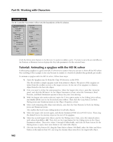
FIGURE 38.9
The IK Controller Parameters rollout sets the boundaries of the IK solution.
Click the Delete Joint button in the Remove IK section to delete a joint. If a bone is set to be an end effector,
the Position or Rotation button displays the Key Info parameters for the selected bone.
Tutorial: Animating a spyglass with the HD IK solver
A telescoping spyglass is a good example of a kinematics system that you can use to show off the HD solver.
The modeling of this example is also easy because it consists of a bunch of cylinders that gradually get smaller.
To animate a spyglass with the HD IK solver, follow these steps:
1. Open the Spyglass.max file from the Chap 38 directory on the DVD.
This file includes a simple spyglass made from primitive objects. The pieces of the spyglass are
linked from the smallest section to the largest section. At the end of the spyglass is a dummy
object linked to the last tube object.
2. First, you need to define the joint properties. Select the largest tube object, open the Hierarchy
panel, and click the IK button. In the Object Parameters rollout, select the Terminator, Bind
Position, and Bind Orientation options to keep this joint from moving.
3. With the largest tube section selected, make the Z Axis option active in the Sliding Joints rollout,
and disable all the axes in the Rotational Joints rollout. Then click the Copy button for both
Sliding Joints and Rotational Joints in the Object Properties rollout.
4. Select each remaining tube object individually, and click the Paste buttons for both the Sliding
Joints and Rotational Joints.
This enables the local Z-axis sliding motion for all tube objects.
5. Select the largest tube section again, and choose Animation ➪ IK Solvers ➪ HD Solver. Then drag
the dotted line to the dummy object at the end of the spyglass.
6. Select the second largest tube object, and for the Sliding Joint Z Axis, select the Limited option
with values from 0.0 to –80. Then click on the Copy button for the Sliding Joints in the Object
Parameters rollout. Then select tubes 3 through 6 individually, and click the Paste button for the
Sliding Joints to apply these same limits to the other tube objects.
7. Click the Auto Key button (N), drag the Time Slider to frame 100 (End), select the Select and Move
button on the main toolbar (W), and drag the dummy object away from the largest tube object.
942