
Page 1312 - Workshop Manual - Aumark (BJ1051)
P. 1312
61-40
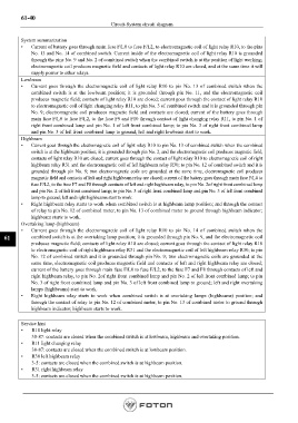
Circuit-System circuit diagram
System summarization
• Current of battery goes through main fuse F/L0 to fuse F/L2, to electromagnetic coil of light relay R10, to the pins
No. 13 and No. 14 of combined switch. Current inside of the electromagnetic coil of light relay R10 is grounded
through the pins No. 9 and No. 2 of combined switch when the combined switch is at the position of light working;
electromagnetic coil produces magnetic field and contacts of light relay R10 are closed, and at the same time it will
supply power to other relays.
Lowbeam
• Current goes through the electromagnetic coil of light relay R10 to pin No. 13 of combined switch when the
combined switch is at the lowbeam position; it is grounded through pin No. 11, and the electromagnetic coil
produces magnetic field; contacts of light relay R10 are closed; current goes through the contact of light relay R10
to electromagnetic coil of light changing relay R11, to pin No. 3 of combined switch and it is grounded through pin
No. 9; electromagnetic coil produces magnetic field and contacts are closed; current of the battery goes through
main fuse F/L0 to fuse F/L2, to the fuse F9 and F10 through contact of light changing relay R11, to pin No. 1 of
right front combined lamp and pin No. 1 of left front combined lamp; to pin No. 3 of right front combined lamp
and pin No. 3 of left front combined lamp to ground; left and right lowbeam start to work.
Highbeam
• Current goes through the electromagnetic coil of light relay R10 to pin No. 13 of combined switch when the combined
switch is at the highbeam position; it is grounded through pin No. 2, and the electromagnetic coil produces magnetic field;
contacts of light relay R10 are closed; current goes through the contact of light relay R10 to electromagnetic coil of right
highbeam relay R31 and the electromagnetic coil of left highbeam relay R30; to pin No. 12 of combined switch and it is
grounded through pin No. 9; two electromagnetic coils are grounded at the same time, electromagnetic coil produces
magnetic field and contacts of left and right highbeam relay are closed; current of the battery goes through main fuse F/L0 to
fuse F/L2, to the fuse F7 and F8 through contacts of left and right highbeam relay, to pin No. 2of right front combined lamp
and pin No. 2 of left front combined lamp; to pin No. 3 of right front combined lamp and pin No. 3 of left front combined
lamp to ground; left and right highbeams start to work.
• Right highbeam relay starts to work when combined switch is at highbeam lamp position; and through the contact
of relay to pin No. 12 of combined meter, to pin No. 13 of combined meter to ground through highbeam indicator;
highbeam starts to work.
Overtaking lamp (highbeam)
• Current goes through the electromagnetic coil of light relay R10 to pin No. 14 of combined switch when the
61 combined switch is at the overtaking lamp position; it is grounded through pin No. 9, and the electromagnetic coil
produces magnetic field; contacts of light relay R10 are closed; current goes through the contact of light relay R10
to electromagnetic coil of right highbeam relay R31 and the electromagnetic coil of left highbeam relay R30; to pin
No. 12 of combined switch and it is grounded through pin No. 9; two electromagnetic coils are grounded at the
same time, electromagnetic coil produces magnetic field and contacts of left and right highbeam relay are closed;
current of the battery goes through main fuse F/L0 to fuse F/L2, to the fuse F7 and F8 through contacts of left and
right highbeam relay, to pin No. 2of right front combined lamp and pin No. 2 of left front combined lamp; to pin
No. 3 of right front combined lamp and pin No. 3 of left front combined lamp to ground; left and right overtaking
lamps (highbeams) start to work.
• Right highbeam relay starts to work when combined switch is at overtaking lamps (highbeams) position; and
through the contact of relay to pin No. 12 of combined meter, to pin No. 13 of combined meter to ground through
highbeam indicator; highbeam starts to work.
Service hint
• R10 light relay
30-87: contacts are closed when the combined switch is at lowbeam, highbeam and overtaking position.
• R11 light changing relay
30-87: contacts are closed when the combined switch is at lowbeam position.
• R30 left highbeam relay
3-5: contacts are closed when the combined switch is at highbeam position.
• R31 right highbeam relay
3-5: contacts are closed when the combined switch is at highbeam position.
Page 1312