
Page 1348 - Workshop Manual - Aumark (BJ1051)
P. 1348
61-76
Circuit-System circuit diagram
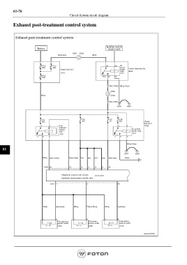
Exhaust post-treatment control system
Exhaust post-treatment control system
Battery Ignition switch
ON/START
White-Red White
Chassis fuse box 1 IG Vehicle body fuse box
power
supply
relay
Green-Yellow White-Black
White
Green-Yellow
fuse box 2
Chassis
Post-
treatment
relay sensor relay
Oxynitride
heating
White-Black
61
White Blue-Yellow White-Black Red Red Red Red White-Blue White
Electronic control unit of post-
treatment (urea system control unit)
White Blue-Black White Yellow-Black White Red-Black
pipeline heater Urea return, Urea suction,
Urea injection,
pipeline heater
pipeline heater
Page 1348