
Page 13 - September 2020 Newsletter
P. 13
September Return to
2020 `Triumphs Live On’ Start
Page 12
www.tswfl.org
Tech Corner-continued
TE ST 4. Checking the Voltage Drop across the solenoid Contacts
To check the voltage drop across the solenoid con tact’s, connect the voltmeter across the two main solenoid
terminals, as shown in Fig. 12. When the operating switch is open, the voltmeter should register battery
voltage. When the operating switch is closed, the voltmeter reading should fall to a fractional value.
A zero or fractional reading on the voltmeter indicates that the high resistance deduced in Test 3 must
be due either to high resistance starter cables or soldered connections. A high reading (similar to that in Test
3) indicates faulty solenoid contacts.
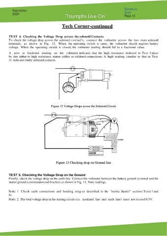
Figure 12 Voltage Drops across the Solenoid Circuit
Figure 13 Checking drop on Ground line
TE ST 5. Checking the Voltage Drop on the Ground
Finally, check the voltage drop on the earth line Connect the voltmeter between the battery ground terminal and the
starter ground (commutator end bracket) as shown in Fig. 13. Note readings.
Note: 1 Check earth connections and bonding strap as described in the "Inertia Starter” section (Tests 7 and
8).
Note: 2. The total voltage drop in the starting circuit (i.e. insulated line and earth line) must not exceed 0.5V.