
Page 11 - September 2020 Newsletter
P. 11
September Return to
2020 `Triumphs Live On’ Start
Page 10
www.tswfl.org
Tech Corner-continued
TE ST 1. Checking the Battery Terminal Voltage under Load Conditions
Connect the voltmeter across the terminals, as shown in Fig. 8 and operate the starter switch. The readings for a
12-volt system depend on the engine capacity, battery size (Ah) and type of starter. A typical figure for
petrol engines is about 100V, and for diesel engine (12V system), 9.OV. A low voltage reading would indicate
excessive current flow in the circuit. The starter should then be removed for bench testing.
Note: If the solenoid operates intermittently during the test or the engine is cranked at a low or irregular speed,
there may be insufficient voltage at the solenoid operating winding terminal or the solenoid is faulty.
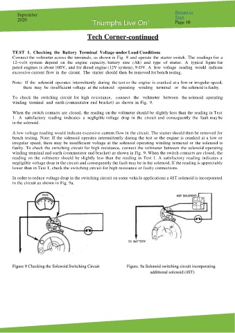
To check the switching circuit for high resistance, connect the voltmeter between the solenoid operating
winding terminal and earth (commutator end bracket) as shown in Fig. 9.
When the switch contacts are closed, the reading on the voltmeter should be slightly less than the reading in Test
1. A satisfactory reading indicates a negligible voltage drop in the circuit and consequently the fault may be
in the solenoid.
A low voltage reading would indicate excessive current flow in the circuit. The starter should then be removed for
bench testing. Note: If the solenoid operates intermittently during the test or the engine is cranked at a low or
irregular speed, there may be insufficient voltage at the solenoid operating winding terminal or the solenoid is
faulty. To check the switching circuit for high resistance, connect the voltmeter between the solenoid operating
winding terminal and earth (commutator end bracket) as shown in Fig. 9. When the switch contacts are closed, the
reading on the voltmeter should be slightly less than the reading in Test 1. A satisfactory reading indicates a
negligible voltage drop in the circuit and consequently the fault may be in the solenoid. If the reading is appreciably
lower than in Test 1, check the switching circuit for high resistance or faulty connections.
In order to reduce voltage drop in the switching circuit on some vehicle applications a 4ST solenoid is incorporated
in the circuit as shown in Fig. 9a.
Figure 9 Checking the Solenoid Switching Circuit Figure. 9a Solenoid switching circuit incorporating
additional solenoid (4ST)