
Page 7 - September 2020 Newsletter
P. 7
September Return to
2020 `Triumphs Live On’ Start
Page 6
www.tswfl.org
Tech Corner-continued
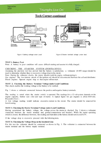
Figure 1 Battery voltage under Load Figure 2 Starter terminal voltage under load
TE ST 1. Battery Test
Note: A battery in poor condition will cause difficult starting and assume it is fully charged.
CHE CKING THE STARTE R SYSTE M (INE RTIA DIVE S)
Assuming the previous test has proved that the battery is satisfactory, a voltmeter (0-40V range) should be
used to determine whether there is excessive voltage drop in the circuit.
Note: During the voltmeter checks, the starter should crank the engine, without starting it.
Gas engines: The low-tension circuit of the ignition coil should be disconnected between the coil and distributor.
Diesel engines: Operate engine stop so that engine will not start.
TE ST 2. Checking the Battery Terminal Voltage under Load Conditions
This check enables the working voltage at the battery to be verified.
Fig. 1 shows a voltmeter connected between the positive and negative battery terminals.
The reading is noted when the starter switch is operated. The readings for a 12-volt system depends on the
engine capacity, battery size (Ah) and type of starter. A typical figure for gas engines is about 10.0 volts.
Proceed to Test 3.
A low voltage reading would indicate excessive current in the circuit. The starter should be removed for
bench testing.
TE ST 3. Checking the Starter Terminal Voltage under Load Conditions
Having ascertained the battery voltage, the voltage across the starter is checked. Fig. 2 shows a voltmeter
connected between the starter terminal and ground (commutator end bracket). When the starter operating
switch is closed, the difference between, this reading and that taken at the battery should not exceed 0.5V.
If the voltage drop is excessive proceed with the following tests.
TE ST 4. Checking the Voltage Drop on the Insulated Line
For this test the voltmeter should be connected as shown in Fig. 3. The voltmeter is connected between the
starter terminal and the battery supply terminal.