
Page 12 - September 2020 Newsletter
P. 12
September Return to
2020 `Triumphs Live On’ Start
Page 11
www.tswfl.org
Tech Corner-continued
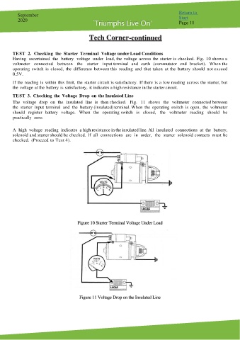
TE ST 2. Checking the Starter Terminal Voltage under Load Conditions
Having ascertained the battery voltage under load, the voltage across the starter is checked. Fig. 10 shows a
voltmeter connected between the starter input terminal and earth (commutator end bracket). When the
operating switch is closed, the difference between this reading and that taken at the battery should not exceed
0.5V.
If the reading is within this limit, the starter circuit is satisfactory. If there is a low reading across the starter, but
the voltage at the battery is satisfactory, it indicates a high resistance in the starter circuit.
TE ST 3. Checking the Voltage Drop on the Insulated Line
The voltage drop on the insulated line is then checked. Fig. 11 shows the voltmeter connected between
the starter input terminal and the battery (insulated) terminal. When the operating switch is open, the voltmeter
should register battery voltage. When the operating switch is closed, the voltmeter reading should be
practically zero.
A high voltage reading indicates a high resistance in the insulated line. All insulated connections at the battery,
solenoid and starter should be checked. If all connections are in order, the starter solenoid contacts must be
checked. (Proceed to Test 4).
Figure 10 Starter Terminal Voltage Under Load
Figure 11 Voltage Drop on the Insulated Line