Page 28 - Priesgaisrine signalizacija FX 3NET_Schneider Electric_Projktavimo instrukcija_ENG
P. 28
Planning Instruction 66571758GB0 Fire Detection 28
7. FX-CLC Conventional detection circuits
7.1 Conventional detection circuit controller (CLC)
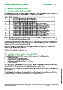
The FX 3NET panels can also be equipped with Conventional Loop Controllers (CLC). The CLC board takes one
loop controller place in the panel. Thus, the following combinations are possible:
LCs CLCs Comment
0 1 No addressable loops, 1 to 16 conventional lines
2 No addressable loops, 17 to 32 conventional lines
3 No addressable loops, 33 to 48 conventional lines
4 No addressable loops, 49 to 64 conventional lines
1 0 2 addressable loops (each 159 + 159 addresses), 0 conventional lines
1 2 addressable loops (each 159 + 159 addresses), 1 to 16 conventional lines
2 2 addressable loops (each 159 + 159 addresses), 17 to 32 conventional lines
3 2 addressable loops (each 159 + 159 addresses), 33 to 48 conventional lines
2 0 4 addressable loops (each 159 + 159 addresses), 0 conventional lines
1 4 addressable loops (each 159 + 159 addresses), 1 to 16 conventional lines
2 4 addressable loops (each 159 + 159 addresses), 17 to 32 conventional lines
3 0 6 addressable loops (each 159 + 159 addresses), 0 conventional lines
1 6 addressable loops (each 159 + 159 addresses), 1 to 16 conventional lines
4 0 8 addressable loops (each 159 + 159 addresses), 0 conventional lines
Note! The total number of detectors and manual call points, connected to one FX panel, may not exceed
512, to fulfill the EN54 standard requirements.
The FX panel handles internally the whole CLC board as one addressable loop and each conventional line as an
address of that loop. Each conventional line can therefore be configured and used just as the conventional zone
module connected to an addressable detection circuit.
It also means that the conventional lines are handled by the user in the same way as the conventional zone
modules, e.g. for disablement/re-enablement.
Each line is by default in its own detection zone.
7.2 Compatible conventional detectors and manual call points
Compatibility of detectors with the CLC conventional line is determined by the following factors:
- Supply voltage range
- Current consumption in standby condition
- Voltage across the detector in alarm condition
- Series resistance (either in the detector or in the base)
- End-of-Line resistor
The voltage supplied by the CLC to the conventional line is 21 VDC to 24 VDC. The maximum allowable voltage
drop in the cable is 21 V minus the lowest operating voltage of the connected devices.
If the line goes through an Exi barrier, the maximum allowed cable resistance and current consumption is less than
© 2009 Schneider Electric. All rights reserved.
for a normal line.
The following table shows the required series resistor for a number of detector voltages (in alarm condition), the
two allowed EOL types and whether or not an Exi barrier is connected to the loop.
Schneider Electric Pelco Finland Oy Kalkkipellontie 6, 02650 Espoo, Finland Telephone: +358 10 446 511 Fax: +358 10 446 5103 www.pelco.com/nordic
Document Number 66571758GB0 49 2011