Page 32 - Priesgaisrine signalizacija FX 3NET_Schneider Electric_Projktavimo instrukcija_ENG
P. 32
Planning Instruction 66571758GB0 Fire Detection 32
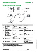
8.3 Cables of serial communication lines and power supply
13 DAPX
FX_
15
18
16
12
13 MCOX 13 REPX 13 FMPX
FX_
18
16 18 18
12
14
17
FXS
Conductors x
No Cable connection Max. length Comments
area
Serial connection 2
- other FX panels 3 x 0.5 mm +
12 shield or 1000 m RS485
- System 1 and 2
System 2 3 x 0.5 mm
Serial connections
and power supply to FXS RS485
2
12 - System 1 and System 2 5 x 0,5 mm + To be calculated Operating voltage range 21...30
17 (RS285) shield separately VDC
- Operating voltage 2 pcs **)
(21…30 VDC)
Serial connections RS485
2
and power supply 7 x 0.5 mm +
13 - INFO (RS485) shield To be calculated Operating voltage range 21...30
18 separately VDC
Operating voltage 2 pcs ***)
(21…30 VDC)
2
2 x 2x0.5 mm +
14 Serial connection 15 m RS232
shield
2
Printer connection 2 x 2 x 0.5 mm +
15 15 m RS232
- Serial data shield
Mains connection:
- 230 ±10% VAC, 50-60 Hz
2
16 Mains supply cable 3 x 1.5 mm - maximum power 160 VA
(FX and FXL)
- maximum power 80 VA (FXM)
- own circuit fuse 10 A
© 2009 Schneider Electric. All rights reserved.
*) For longer distances see Part 3: Additional Information
**) Communication and power supply in the same cable. Doubled wires.
***) Communication and power supply (2 pcs) in the same cable. Doubled wires.
Schneider Electric Pelco Finland Oy Kalkkipellontie 6, 02650 Espoo, Finland Telephone: +358 10 446 511 Fax: +358 10 446 5103 www.pelco.com/nordic
Document Number 66571758GB0 49 2011