Page 29 - Priesgaisrine signalizacija FX 3NET_Schneider Electric_Projktavimo instrukcija_ENG
P. 29
Planning Instruction 66571758GB0 Fire Detection 29
EOL resistor, Exi 4k7, 5%, not Exi 2k94, 1%, not Exi 4k7, 5%, Exi 2k94, 1%, Exi
Max cable resistance 100Ω 100Ω 50Ω 50Ω
Max detector load 1,8 mA 4,0 mA 1,5 mA 3,0 mA
8V 50 – 1000Ω 50 - 550Ω 10 - 700Ω 10 - 320Ω
5V 110 - 1300Ω 110 - 750Ω 150 - 1050Ω 170 - 550Ω
3V 140 - 1500Ω 150 - 880Ω 250 - 1250Ω 280 - 710Ω
1V 180 - 1700Ω 190 - 1010Ω 340 - 1500Ω 380 - 880Ω
0V 200 - 1800Ω 210 - 1070Ω 390 - 1600Ω 440 - 960Ω
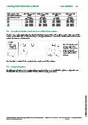
7.3 Conventional detection circuit structure and End-of-Line resistors
Each line (conventional detection circuit) of the CLC is terminated with an End-of-Line resistor. The value of this
resistor can be either 4k7 or 2k94, depending on the type of detectors connected to the line and the alarm series
resistor the detector or its base has.
Max 32 detectors and
manual call points
together. The number
may be reduced
further by the current
consumption of the
devices.
See the table in section 7.2 for required series resistors and EOL resistors.
7.4 Configurable options
For different applications, the operation of the conventional line can be modified through the configuration tool
WinFX 3NET. See the document 6657 1783GBx FX3Net Configuration Data.
© 2009 Schneider Electric. All rights reserved.
Schneider Electric Pelco Finland Oy Kalkkipellontie 6, 02650 Espoo, Finland Telephone: +358 10 446 511 Fax: +358 10 446 5103 www.pelco.com/nordic
Document Number 66571758GB0 49 2011