
Page 10 - Railways
P. 10
RAILWAYS The excellence of collaboration www.moniterra.engineering RAILWAYS
It should be noted that the measurements were tied to the 3. WHY WAS THE GRP SYSTEM SELECTED FOR The way to deal with this problem was to take the necessary Often, that was not an adequate solution and it was necessary
already existing trigonometrical network within the tunnel, after THE SPECIFIC PROJECT? protection measures and the increased attention by our crews. to wait for certain works to end in order to start measurements
it was first checked. again.
The project requirements and the large volume of the works b) As regards the phase of track adjustment-tracing, due to
• Above-ground: necessitated highly precise measurements in the shortest the very high requirements, the weather conditions during the 6.) EQUIPMENT USED:
Here the monitoring of micro-movements pertained to the possible time. The GRP system and the appropriately trained summer were an inhibitory factor for measurement accuracy. • GRP 1000 AMBERG track geometry control system
buildings and any settlements of the paving above the specific staff made both these possible and the high density of the This was dealt with by providing the best possible protection GRP 5000 AMBERG clearance control system
to the instruments from solar radiation and high temperatures, •
tunnel. In order to proceed to the measurement stage, a new measurements, so that the final result reflects uniformity and
horizontal and elevation network had to be established and continuity, and the construction conforms, to the greatest and with very frequent and close set ups of the geodetic station • Geodetic Stations LEICA 1201, 1’’,+/- (2mm+2ppm) ,
in relation to the GRP, thus minimizing possible errors.
resolved first, this time above ground the tunnel. possible degree, with the study drawn up in advance. LEICA 2003, 0,5’’, +/- (1mm+1ppm) , and Trimble S6 High
Therefore, angle measurements and levelling of the established Another advantage of surveying and concurrently tracing c) The narrowness of the space at the project limited the Precision, 1’’, +/- (1mm+1ppm).
fixed points-peaks on the road directly above the tunnel were with the GRP system, was that the survey crew could consist of flexibility of movement both outside, but especially inside the • Digital Level TRIMBLE Dini (0.3mm/km)
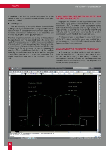
“Monastiraki – Attiki” tunnel. As a result:
made. Then a secondary trigonometric network was established a single person, as the geodetic station operates automatically, • Laser Scanner 5003 AMBERG
and resolved with the corresponding angle measurements, i.e. thus economizing human resources. - The reference targets and controls were destroyed by
reference targets that were installed at points outside the zone passing cars and machinery, and therefore needed to be • 4 dual frequency TRIMBLE R8 and 7 single frequency
of influence of the works, where the control measurements reinstalled and included again in the system. TRIMBLE R3 GPS.
were tied. These controls were installed on all the buildings 4.) WHAT WERE THE PRESENTED PROBLEMS?
inside the zone of influence of the works and they were the a) The main problem that had to be dealt with was that - The restriction of visibilities during the orientation of the
geodetic station and the monitoring due to the existing
object of the measurements for any micro-movements. Their during the establishment of the trigonometric network along
results, respectively, were sent to the construction company the track, and the surveying of their existing conditions, the machinery, tools or workers.
daily. trains operated normally, and thus the surveying works were The only way to deal with this problem was through correct
carried out with increased risk because of the frequent routes scheduling and coordination of the works in the right sequence.
and the powered railway tracks.
The Principle:
ACCURATE RAIL TRACK GEOMETRY
TAMPING LASER SCANNING
SLAB TRACK GRP 5000
BALLASTED TRACK
GRP 1000
IMS 1000 Structure Envelope Tunnel
IMS 3000 PROFILES CLEARANCE INSPECTION
10 11