
Page 5 - Railways
P. 5
RAILWAYS The excellence of collaboration www.moniterra.engineering RAILWAYS
APPLICATION AREAS
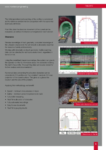
Tamping / Ballasted Track / Slab Track The initial georeferenced scanning of the profiles is considered
as the reference section line for comparison with the scans that
eventually will follow.
Using the Amberg FX System we can provide Correction data
for tamping machine for the purposes of Construction, Renewal
or Maintenance of line From this data the absolute movement of the tunnel can be
By displaying all track parameter in real time as well as the evaluated, as well as the relative convergences in each section.
deviations to design we get full control during the work.
Clearance
Benefits:
GRP System FX Besides knowledge of track geometry, complete knowledge of Clearance Sections
the utilizable clearance in the rail network is absolutely essential
• Highest productivity & reliability, approx. 1000 - 2500 m/h for reasons of safety and economy.
• Guaranteed mm accuracy Working with kinematic or stop & go mode, mobile scanning
• Quick and precise determination of track correction data data can be collected for rail tracks environment, regardless in
• Just-in-time results tunnel or not.
• Track geometry assessments
• Direct export of correction data to tamping machines Using the predefined clearance envelope, the system can give to
• During track laying, track adjustment and concreting the operator on-the-fly information about the obstacles violating
• Set out & check & documentation the train’s free profile. The scanning data can be also stored for
• Survey productivity to track works rate further analysis and documentation.
• Compliance reporting
Athens metro slab track Numerical data concerning the allocated obstacles can be Clearance projection map
presented in 2-D profiles and “iso-violation” curves in 2-D map
Profiles projection of the tunnel surface. This gives at a glance the
location and the size of the problem.
Since the reference axis is accurately determined, a laser
scanner is being added on the trolley,that can measure Applying this methodology we benefit:
either in Stop & go or Kinematic mode. The laser scanner’s
measurements, combined with the measured rail track can give
a very dense georeferenced and accurate point cloud. • Speed – minimum time presence in track
• Safety – minimum personnel presence in track
• Full profile measuring
From that point cloud we can get: section profiles for
monitoring deformations in tunnel, envelope clearance and • Real Time allocation of obstacles
allocation of obstacles, and, finally, full tunnel high definition • Fully automated recordings
imaging for tunnel inspection. Tamping data • Easy to use documents Tempi rails clearance control
• Real Time gauging results
Along the tunnel walls we preinstall control targets with
accurately determined coordinates, within less than 50m
between 2 sequel targets.
Also along the tunnel we can use marked points on specific
chainages to indicate where a profile should be measured.
Using stop & go mode, we scan the predefined profiles, in order
to collect redundant data for statistical analysis of the point
cloud, as the laser scanner itself gives noise data at the edge of
deformation monitoring standards for tunnels.
Ikonio railways Clearance on the fly
4 5