Page 800 - UK Air Operations Regulations 201121
P. 800

~          Regulation SPO - ANNEX VIII - Specialised Operations                                              n trik

                                          --· -..-·-··- ····-·- -· - ....----···----·- -·-..---,-- -··----- ··- ····
                                                   ·
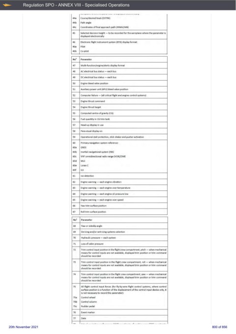
                                      44a   Course/desired track (DSTRK)
                                      44b   Path angle
                                      44c   Coordinates of final approach path (IRNAV/IAN)
                                      45   Selected decision height - t.o be reco rded for the aeroplane w here the parameter is
                                          displayed electronically
                                      46   Electronic fiight instrument system (EFIS)  display format:
                                      46a   Pilot
                                      46b   Co-pilot
                                      No'   Parameter
                                      47   Multi-function/engine/alerts display format
                                      48   AC electrical  bu5 status - each bus
                                      49   DC electrica I bus status - each bus
                                      50   Engine bleed valve pos.it io n
                                      51   Auxiliary power unit (APU) bleed valve position
                                      52   Com puter failure  - (all critical flight and engine control systems)
                                      53   Engine thrust command
                                      54   Engine thrust target
                                      55   Computed centre of gravity (CG)
                                      56   fu el quant ity in CG t rim tank
                                      57   Head-up display in use
                                      58   Para vi.s.ua1 di.s.play on
                                      59   Operationa l stall protection, stick shaker and pus.her activation
                                      60   Primary navigation system refe rence:
                                      60a   GNSS
                                      60b   Inertial navigational system (INS)
                                      60c   VHF omnidirectional radio range {VOR)/DME
                                      60d   Ml.S
                                      60e   Loran C
                                      60f   ILS
                                      61   Ice detection
                                      62   Engine wam ing - each engine vibration
                                      63   Engine wam ing - each engine ove r tem perature
                                      64   Engine warn ing -  each engine oil pressure low
                                      65   Engine warn ing -  each engine ove r speed
                                      66   Yaw t rim surface position
                                      67   Roll t rim surface position
                                      No   Parameter
                                      68   Yaw or s.ideslip angle
                                      69   De-icing and/or anti-icing systems selection
                                      70   Hydraulic pressure - each system
                                      71   Loss of cabin pressure
                                      72   Trim control input position in the flight  crew compartment, pitch - when mechanical
                                          means for control inputs are not available, displayed trim  position or t rim command
                                          should be recorded
                                      73   Trim control input  position in t he flight cr ew compartment, roll - when mechanical
                                          means for control inputs are not available, displayed trim  position or t rim command
                                          should be recorded
                                      74   Trim control input position in the flight crew compartment , yaw - wh en mechanical
                                          means for control inputs are not  available, displayed trim  position or t rim command
                                          should be  recorded
                                      75   All flight  control  input  forces {for fly-by-wire  flight  control systems, w here  control
                                          surface position is a function of th e disp lacement of th e control input device onJy,  it
                                          is not necessary to record t his  parameter):
                                      75a   Control w heel
                                      75b   Control column
                                      75c   Rudder pedal
                                      76   Event marker
                                      77   Date
                                      ' "   . _._ ___  t  -- - ·-.L:- - __ _.L ___ _ _  __  f •• • n l  - -  _ _ .._. ___ ... _  _ r.  ___ . ._. __  ----- f r- n.rl  -- __ .._. ___ ..__
     20th November 2021                                                                                     800 of 856
   795   796   797   798   799   800   801   802   803   804   805