
Page 161 - Libro vascular I
P. 161
Chap-11.qxd 29~8~04 14:49 Page 152
152
PERIPHERAL VASCULAR ULTRASOUND
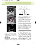
BA
T
F
A: B-mode image of a dissecting aortic aneurysm. In this example the true (T) and false (F)
lumens are seen. B: Color flow imaging demonstrates flow in the false flow lumen (arrow). C: In this example, a dissection into the thrombus and the vessel wall has occurred (arrow).
MEASUREMENTS
It is important to make accurate diameter measure- ments of the aorta, especially if a patient is having serial follow-up scans to monitor the size of an
A
Spine
The anteroposterior diameter of a tortuous aorta may be overestimated because of measurement in
the wrong scan plane. In this example, the aorta is deflecting in an anterior direction. Scanning in a transverse plane along line A will result in an oblique image of the aorta, and the anteroposterior diameter will be overestimated. The transducer should be tilted to obtain the correct line of measurement along line B.
An example of this problem is shown in Figure 11.6.
Figure 11.9
aneurysm. The UK Small Aneurysm Trial Participants (1998) showed that the error between operators was in the region of 0.2cm for aneurysms measur- ing 4–5.5 cm in diameter. This section explains how to make diameter measurements of the aorta and identifies the potential pitfalls that may be involved. It should be noted that some of these measurements may not be necessary for screening scans.
Aorta diameter
Transverse scanning plane
The maximum diameter of the aorta should be measured in the anteroposterior (AP) direction from the outer anterior wall to the outer posterior wall (Fig. 11.6). If an aneurysm is present, overestimation of its size can occur if oblique measurements are made, due to tortuosity or folding of the aorta (Figs 11.6 and 11.9). Measurements of the lateral diame- ter of the aneurysm (i.e., from lateral wall to lateral wall) in a transverse scan plane are prone to error as the lateral vessel walls are parallel to the ultrasound beam, which therefore produces a very poor image (see Ch. 2). The thickness of any thrombus can also
B
Figure 11.8
C
