
Page 22 - Libro vascular I
P. 22
Chap-02.qxd 29~8~04 13:20 Page 13
Skin Tissue interface
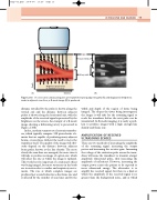
Artery walls
ICA
ECA
CCA
Brightness proportional to amplitude of echoes
Distance
(A)
distance travelled by the pulse is shown along the vertical axis and the distance between adjacent pulses is shown along the horizontal axis, with the amplitude of the received signal represented by the brightness on the screen. An example of a B-mode image showing a bifurcating artery is presented in Figure 2.10B.
In fact, modern scanners use electronic transduc- ers, which typically comprise 128 piezoelectric ele- ments that are capable of producing many adjacent beams, or scan lines, without the need to move the transducer itself. The quality of the image will obvi- ously depend on the distance between adjacent beam paths, known as the line density. The more closely the scan lines are arranged, the more time it will take to produce an image of a given size, which will affect the rate at which the image is updated. This would not be important if a stationary object was being imaged, but most structures in the body are in motion due to cardiac and respiratory move- ments. The rate at which complete images are produced per second is known as the frame rate and is affected by the number of scan lines and by the
(B)
ULTRASOUND AND IMAGING
13
If consecutive ultrasound pulses are transmitted along adjacent paths (A) and displayed in brightness mode in adjacent scan lines, a B-mode image (B) is produced.
Figure 2.10
width and depth of the region of tissue being imaged. The deeper the tissue being interrogated, the longer it will take for the returning signal to reach the transducer before the next pulse can be transmitted. In B-mode imaging, it is rarely a prob- lem to produce images with a high enough line density and frame rate.
AMPLIFICATION OF RECEIVED
ULTRASOUND ECHOES
There are two methods of increasing the amplitude of the returning signal: increasing the output power and increasing the receiver gain. Increasing the voltage of the excitation pulse across the trans- ducer will cause the transducer to transmit a larger amplitude ultrasound pulse, thus increasing the amplitude of reflections. However, increasing the output power causes the patient to be exposed to more ultrasound energy. The alternative is to amplify the received signal, but there is a limit at which the amplitude of the received signal is no greater than the background noise, and at which
Depth
