
Page 174 - Programmable Logic Controllers, Fifth Edition
P. 174
Input TOF SOL A
TIMER OFF DELAY
Timer T4:0 EN
Time base 1.0 Motor
Preset 10
Accumulated 0 DN
T4:0
EN
T4:0 Full
sensor
switch
T T
T4:0 Empty
sensor
switch
DN SOL B
Figure 7-45 Off-delay timer ladder logic program for Start/stop
Problem 10. control station
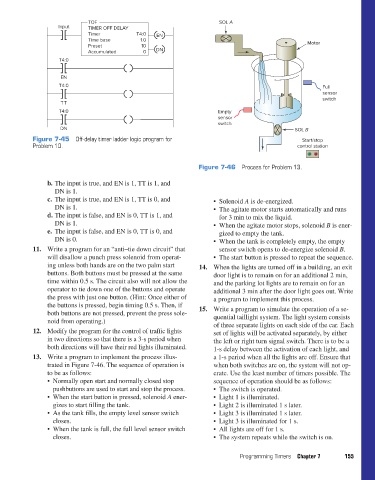
Figure 7-46 Process for Problem 13.
b. The input is true, and EN is 1, TT is 1, and
DN is 1.
c. The input is true, and EN is 1, TT is 0, and • Solenoid A is de-energized.
DN is 1. • The agitate motor starts automatically and runs
d. The input is false, and EN is 0, TT is 1, and for 3 min to mix the liquid.
DN is 1. • When the agitate motor stops, solenoid B is ener-
e. The input is false, and EN is 0, TT is 0, and gized to empty the tank.
DN is 0. • When the tank is completely empty, the empty
11. Write a program for an “anti–tie down circuit” that sensor switch opens to de-energize solenoid B.
will disallow a punch press solenoid from operat- • The start button is pressed to repeat the sequence.
ing unless both hands are on the two palm start 14. When the lights are turned off in a building, an exit
buttons. Both buttons must be pressed at the same door light is to remain on for an additional 2 min,
time within 0.5 s. The circuit also will not allow the and the parking lot lights are to remain on for an
operator to tie down one of the buttons and operate additional 3 min after the door light goes out. Write
the press with just one button. (Hint: Once either of a program to implement this process.
the buttons is pressed, begin timing 0.5 s. Then, if
both buttons are not pressed, prevent the press sole- 15. Write a program to simulate the operation of a se-
noid from operating.) quential taillight system. The light system consists
of three separate lights on each side of the car. Each
12. Modify the program for the control of traffic lights set of lights will be activated separately, by either
in two directions so that there is a 3-s period when the left or right turn signal switch. There is to be a
both directions will have their red lights illuminated. 1-s delay between the activation of each light, and
13. Write a program to implement the process illus- a 1-s period when all the lights are off. Ensure that
trated in Figure 7-46. The sequence of operation is when both switches are on, the system will not op-
to be as follows: erate. Use the least number of timers possible. The
• Normally open start and normally closed stop sequence of operation should be as follows:
pushbuttons are used to start and stop the process. • The switch is operated.
• When the start button is pressed, solenoid A ener- • Light 1 is illuminated.
gizes to start filling the tank. • Light 2 is illuminated 1 s later.
• As the tank fills, the empty level sensor switch • Light 3 is illuminated 1 s later.
closes. • Light 3 is illuminated for 1 s.
• When the tank is full, the full level sensor switch • All lights are off for 1 s.
closes. • The system repeats while the switch is on.
Programming Timers Chapter 7 155
pet73842_ch07_131-155.indd 155 05/11/15 4:22 PM