
Page 173 - Programmable Logic Controllers, Fifth Edition
P. 173
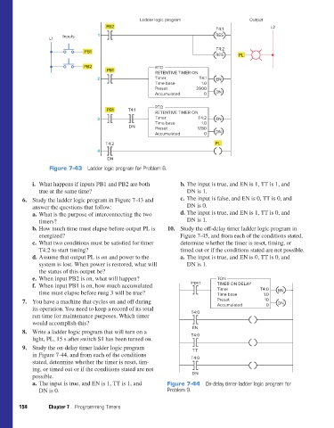
PB2         Ladder logic program                    Output  L2
                                                                                       T4:1
                               Inputs       1                                          RES
                          L1
                                                                                        T4:2
                                       PB1
                                                                                       RES      PL
                                       PB2                       RTO
                                               PB1
                                                                 RETENTIVE TIMER ON
                                            2                    Timer           T4:1  EN
                                                                 Time base        1.0
                                                                 Preset         2900
                                                                 Accumulated       0   DN

                                                                 RTO
                                               PB1     T4:1
                                                                 RETENTIVE TIMER ON
                                            3                    Timer           T4:2  EN
                                                                 Time base        1.0
                                                       DN        Preset          1780
                                                                 Accumulated       0   DN

                                               T4:2                                    PL
                                            4
                                                DN
                          Figure 7-43  Ladder logic program for Problem 6.

                    i.  What happens if inputs PB1 and PB2 are both       b. The input is true, and EN is 1, TT is 1, and
                       true at the same time?                                DN is 1.
                 6. Study the ladder logic program in Figure 7-43 and     c. The input is false, and EN is 0, TT is 0, and
                    answer the questions that follow:                        DN is 0.
                    a. What is the purpose of interconnecting the two     d. The input is true, and EN is 1, TT is 0, and
                       timers?                                               DN is 1.
                    b. How much time must elapse before output PL is   10. Study the off-delay timer ladder logic program in
                       energized?                                         Figure 7-45, and from each of the conditions stated,
                    c. What two conditions must be satisfied for timer    determine whether the timer is reset, timing, or
                       T4:2 to start timing?                              timed out or if the conditions stated are not possible.
                    d. Assume that output PL is on and power to the       a. The input is true, and EN is 0, TT is 0, and
                       system is lost. When power is restored, what will     DN is 1.
                       the status of this output be?
                    e. When input PB2 is on, what will happen?                          TON
                    f.  When input PB1 is on, how much accumulated            Input     TIMER ON DELAY
                       time must elapse before rung 3 will be true?                     Timer          T4:0   EN
                                                                                        Time base
                                                                                                         1.0
                 7. You have a machine that cycles on and off during                    Preset           10   DN
                    its operation. You need to keep a record of its total               Accumulated       0
                    run time for maintenance purposes. Which timer            T4:0
                    would accomplish this?
                                                                               EN
                 8. Write a ladder logic program that will turn on a
                    light, PL, 15 s after switch S1 has been turned on.       T4:0
                 9. Study the on-delay timer ladder logic program              T T
                    in Figure 7-44, and from each of the conditions           T4:0
                    stated, determine whether the timer is reset, tim-
                    ing, or timed out or if the conditions stated are not
                    possible.                                                 DN
                    a. The input is true, and EN is 1, TT is 1, and   Figure 7-44  On-delay timer ladder logic program for
                       DN is 0.                                      Problem 9.

               154        Chapter 7  Programming Timers


          pet73842_ch07_131-155.indd   154                                                                              05/11/15   4:22 PM