
Page 311 - Programmable Logic Controllers, Fifth Edition - Mobile version
P. 311
13.9 Troubleshooting
• Flashing during operation indicates a major error
either in the processor, chassis, or memory.
In the event of a PLC fault, you should employ a care-
ful and systematic approach to troubleshoot the system to • On steady indicates that a fatal error is present (no
resolve the problem. PLCs are relatively easy to trouble- communications).
shoot because the control program can be displayed on • Off indicates there are no errors.
a monitor and watched in real time as it executes. If a
control system has been operating, you can be fairly con- BATT (Red)
fident of the accuracy of the program logic. For a system • On steady indicates the battery voltage has fallen
that has never worked or is just being commissioned, pro- below a threshold level, or the battery is missing or
gramming errors should be considered. not connected.
When a problem occurs, the first step in the trouble- • Off indicates that the battery is functional.
shooting procedure is to identify the problem and its
source. The source of a problem can generally be nar- The processor then monitors itself continually for any
rowed down to the processor module, I/O hardware, wir- problems that might cause the controller to execute the
ing, machine inputs or outputs, or ladder logic program. user program improperly. Depending on the controller, a
Once a problem is recognized, it is usually quite simple to set of fault relay contacts may be available. The fault relay
deal with. The following sections will deal with trouble- is controlled by the processor and is activated when one or
shooting these potential problem areas. more specific fault conditions occur. The fault relay con-
tacts are used to disable the outputs and signal a failure.
Processor Module Most PLCs incorporate a watchdog timer to moni-
The processor is responsible for the self-detection of po- tor the scan process of the system. The watchdog timer
tential problems. It performs error checks during its op- is usually a separate timing circuit that must be set and
eration and sends status information to indicators that are reset by the processor within a predetermined period. The
normally located on the front of the processor module. watchdog timer circuit monitors how long it takes the
You can diagnose processor faults or obtain more detailed CPU to complete a scan. If the CPU scan takes too long, a
information about the processor by accessing the proces- watchdog major error will be declared. PLC user manuals
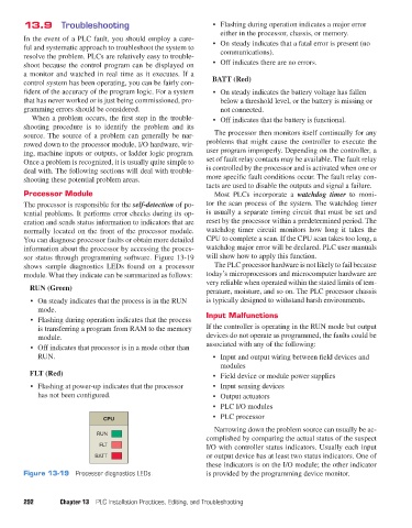
sor status through programming software. Figure 13-19 will show how to apply this function.
shows sample diagnostics LEDs found on a processor The PLC processor hardware is not likely to fail because
module. What they indicate can be summarized as follows: today’s microprocessors and microcomputer hardware are
very reliable when operated within the stated limits of tem-
RUN (Green) perature, moisture, and so on. The PLC processor chassis
• On steady indicates that the process is in the RUN is typically designed to withstand harsh environments.
mode.
• Flashing during operation indicates that the process Input Malfunctions
is transferring a program from RAM to the memory If the controller is operating in the RUN mode but output
module. devices do not operate as programmed, the faults could be
• Off indicates that processor is in a mode other than associated with any of the following:
RUN. • Input and output wiring between field devices and
modules
FLT (Red) • Field device or module power supplies
• Flashing at power-up indicates that the processor • Input sensing devices
has not been configured. • Output actuators
• PLC I/O modules
CPU • PLC processor
Narrowing down the problem source can usually be ac-
RUN
complished by comparing the actual status of the suspect
FLT I/O with controller status indicators. Usually each input
BATT or output device has at least two status indicators. One of
these indicators is on the I/O module; the other indicator
Figure 13-19 Processor diagnostics LEDs. is provided by the programming device monitor.
292 Chapter 13 PLC Installation Practices, Editing, and Troubleshooting
pet73842_ch13_281-304.indd 292 03/11/15 7:22 PM