
Page 312 - Programmable Logic Controllers, Fifth Edition - Mobile version
P. 312
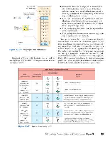
LED indicator
                                     not illuminated  Input module         •  When input hardware is suspected to be the source
                                                                             of a problem, the first check is to see if the status
                                                                             indicator on the input module illuminates when it is
                                  Input pushbutton                           receiving power from its corresponding input device
                                   contacts closed
                                                                             (e.g., pushbutton, limit switch).
                       +24 V DC                         IN 0               •  If the status indicator on the input module does not
                                                        IN 1                 illuminate when the input device is on, take a volt-
                                                        IN 2                 age measurement across the input terminal to check
                                                                             for the proper voltage level.
                        Check input  ?                  IN 3
                        voltage level  –     +                             •  If the voltage level is correct, then the input module
                                                        IN 4
                                                                             should be replaced.
                                                        IN 5
                                                                           •  If the voltage level is not correct, power supply, wir-
                                                        IN 6                 ing, or input device may be faulty.
                                                        IN 7
                                                                           If the programming device monitor does not show the
                                                      DC COM             correct status indication for a condition instruction, the
                           Common
                                                      DC COM             input module may not be converting the input signal prop-
                                                                         erly to the logic level voltage required by the processor
                                                                         module. In this case, the input module should be replaced.
                   Figure 13-20  Checking for input malfunctions.
                                                                         If a replacement module does not eliminate the problem
                                                                         and wiring is assumed to be correct, then the I/O rack,
                                                                         communication cable, or processor should be suspected.
                     The circuit of Figure 13-20 illustrates how to check for   Figure 13-21 shows a typical input device troubleshooting
                   discrete input malfunctions. The steps taken can be sum-  guide. This guide reviews condition instructions and how
                   marized as follows:                                   their true/false status relates to external input devices.


                                                          Input device troubleshooting guide
                                                             Monitor display
                                                              status indicator
                                  Input      Input module                                    Possible
                              device condition  status indicator                             fault(s)

                                                            True       False    None - correct indications
                               Closed — ON      ON
                              24 V DC input
                                                           False       True
                               Open — OFF       OFF                             None - correct indications
                               0 V DC input

                                                           False       True    Sensor condition, input voltage, status indicator
                               Closed — ON      ON                             are correct. Ladder instructions have incorrect
                               24 V DC input                                   indications. Input module or processor fault.
                                                           False       True    Status indicator and instructions agree but not
                               Closed — ON      OFF                            with the sensor condition. Open field device
                               0 V DC input                                    or wiring.

                                                            True       False   Sensor condition, input voltage, status indicator
                               Open — OFF       OFF                            are correct. Ladder instructions have incorrect
                               0 V DC input                                    indications. Input module or processor fault.
                                                           True        False   Input voltage, status indicator, and ladder
                               Open — OFF       ON                             instructions agree but not with sensor condition.
                               24 V DC input                                   Short circuit in the field device or wiring.

                             Figure 13-21  Input troubleshooting guide.


                                                          PLC Installation Practices, Editing, and Troubleshooting  Chapter 13  293


          pet73842_ch13_281-304.indd   293                                                                              03/11/15   7:22 PM