
Page 377 - Programmable Logic Controllers, Fifth Edition - Mobile version
P. 377
Part 3 Programming
Timers
Timer Predefined Structure Part Objectives
Timers are used to turn outputs on and off after a time
delay, turn outputs on or off for a set amount of time, and After completing this part, you will be able to:
keep track of the time an output is on or off. The timer • Understand ControlLogix timer tags and their members
address in the SLC 500 controller is a data table address • Utilize status bits from timers in logic
or symbol, whereas the timer address in the ControlLogix • Develop ladder logic programs using ControlLogix
controller is a predefined structure of the TIMER data timers
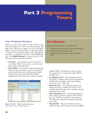
type. The TIMER structure is shown in Figure 15-49.
Timer parameters and status bits include:
• Tag Name—User-friendly tag name for the timer
(e.g., Pump_Timer). If you want to use a timer, you
must create a tag of type timer.
• Preset (PRE)—The number of time increments that
the timer must accumulate to reach the desired time number (DINT). The time base is always 1 msec.
delay. Specifies the value (in milliseconds) which For example, for a 3 second timer, enter 3000 for
the timer must reach before the done bit (DN) the PRE value.
changes state. The preset value is stored as a binary
• Accumulator (ACC)—The accumulator value is
the number of milliseconds the instruction has been
Data Type: TIMER enabled. The accumulator value stops changing
when ACC value 5 PRE value.
Name: Pump_Timer
• Enable Bit (EN)—The enable bit indicates the
Description:
timing instruction is enabled. The EN bit is true
when the rung input logic is true, and false when the
Members: Data Type Size: 12 byte(s)
rung input logic is false.
Name Data Type Style Description
PRE DINT Decimal • Timer Timing Bit (TT)—The timing bit indicates
ACC DINT Decimal that a timing operation is in process. The TT bit is
EN BOOL Decimal true only when the accumulator is incrementing.
TT BOOL Decimal
DN BOOL Decimal TT remains true until the accumulator reaches the
preset value.
Figure 15-49 TIMER predefined structure. • Done Bit (DN)—The done bit indicates that ac-
Source: Image Courtesy of Rockwell Automation, Inc. cumulated value (ACC) is equal to the preset (PRE)
358
pet73842_ch15_333-394.indd 358 03/11/15 7:33 PM