
Page 378 - Programmable Logic Controllers, Fifth Edition - Mobile version
P. 378
value. The DN bit signals the end of the timing
Diverter gate
process by changing states from false-to-true or solenoid delay timer
from true-to-false depending on the type of TIMER TON
instruction used. The DN bit is the most commonly TIMER ON DELAY EN
Timer
Solenoid_Delay
used timer status bit. Preset 3000 DN
Accum 0
On-Delay Timer (TON)
The on-delay timer (TON) is a nonretentive output in-
struction used when the application requires an action to
occur at some time after the rung conditions for the timer
become true. The ControlLogix TON on-delay instruction
and timer selection toolbar are shown in Figure 15-50.
When you want to use a timer, you must create a tag of
type TIMER (it is a predefined data type) and enter the
preset and the accumulated value. The tag must be defined
before the preset and accumulated values can be entered.
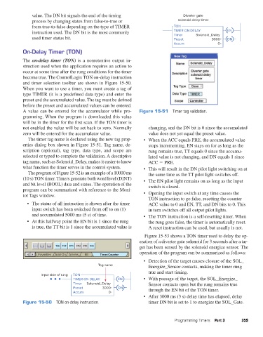
A value can be entered for the accumulator while pro- Figure 15-51 Timer tag validation.
gramming. When the program is downloaded this value
will be in the timer for the first scan. If the TON timer is
not enabled the value will be set back to zero. Normally changing, and the DN bit is 0 since the accumulated
zero will be entered for the accumulator value. value does not yet equal the preset value.
The timer tag name is declared using the new tag prop- • When the ACC equals PRE, the accumulated value
erties dialog box shown in Figure 15-51. Tag name, de- stops incrementing, EN stays on for as long as the
scription (optional), tag type, data type, and scope are rung remains true, TT equals 0 since the accumu-
selected or typed to complete the validation. A descriptive lated value is not changing, and DN equals 1 since
tag name, such as Solenoid_Delay, makes it easier to know ACC 5 PRE.
what function the timer serves in the control system. • This will result in the DN pilot light switching on at
The program of Figure 15-52 is an example of a 10000 ms the same time as the TT pilot light switches off.
(10 s) TON timer. Timers generate both word level (DINT) • The EN pilot light remains on as long as the input
and bit level (BOOL) data and status. The operation of the switch is closed.
program can be summarized with reference to the Moni-
tor Tags window. • Opening the input switch at any time causes the
TON instruction to go false, resetting the counter
• The status of all instruction is shown after the timer ACC value to 0 and EN, TT, and DN bits to 0. This
input switch has been switched from off to on (1) in turn switches off all output pilot lights.
and accumulated 5000 ms (5 s) of time. • The TON instruction is a self-resetting timer. When
• At this halfway point the EN bit is 1 since the rung the rung goes false, the timer is automatically reset.
is true, the TT bit is 1 since the accumulated value is A reset instruction can be used, but usually is not.
Figure 15-53 shows a TON timer used to delay the op-
eration of a diverter gate solenoid for 3 seconds after a tar-
TON TOF RTO CTU CTD RES get has been sensed by the solenoid energize sensor. The
operation of the program can be summarized as follows:
Favorites Add-On Alarms Bit Timer/Counter
• Detection of the target causes closure of the SOL_
Tag name Energize_Sensor contacts, making the timer rung
true and start timing.
Input side of rung TON
TIMER ON DELAY EN • With passage of the target, the SOL_Energize_
Timer Solenoid_Delay Sensor contacts open but the rung remains true
Preset 3000 DN through the EN bit of the TON timer.
Accum 0
• After 3000 ms (3 s) delay time has elapsed, delay
Figure 15-50 TON on-delay instruction. timer DN bit is set to 1 to energize the SOL_Gate.
Programming Timers Part 3 359
pet73842_ch15_333-394.indd 359 03/11/15 7:33 PM