
Page 375 - Programmable Logic Controllers, Fifth Edition - Mobile version
P. 375
PART 2 REVIEW QUESTIONS
1. What operations are performed by the processor 6. The value of an OTE instruction as it appears in
during the program scan? the Monitor Tags window is 1. Explain what this
2. With a ControlLogix processor, I/O updates occur means as far as the status of a real-world field out-
asynchronously. Explain what this means. put and programmed XIC and XIO instructions
3. In ladder logic programming into what two broad associated with this tag are concerned.
categories can instruction types be classified? 7. Define a tag in the ControlLogix system.
4. A field input switch is examined using an XIC 8. What advantage do tag-based addressing systems
instruction. have over rack/slot types?
a. What is the value (0 or 1) stored in its memory 9. How is an internal relay programmed in the
bit when the switch is opened and closed? ControlLogix system?
b. What is the state of the instruction (true or false) 10. The output latch instruction is a retentive output
when the switch is opened and closed? instruction. Explain what retentive means.
5. A field input switch is examined using an XIO 11. The ControlLogix ONS instruction is a one-shot
instruction. instruction. Explain what this means.
a. What is the value (0 or 1) stored in its memory
bit when the switch is opened and closed?
b. What is the state of the instruction (true or false)
when the switch is opened and closed?
PART 2 PROBLEMS
1. Modify the original ControlLogix start/stop motor 24 VDC 120 VAC
control program (Figure 15-34) with a second
start and stop button added to the program. The Temp Sw
additional start button is to be connected to pin Relay
1 and the stop button to pin 2 of the digital input Latch contact
coil
module. Float Sw 1 Float Sw 2 L Alarm
2. Extend control of the original ControlLogix internal
relay program (Figure 15-38) used to control a room Sensor Sw 1
light from 3 entrances to 4. The additional single-
pole switch is to be connected to pin 4 of the digital
input module. Pressure
Sw
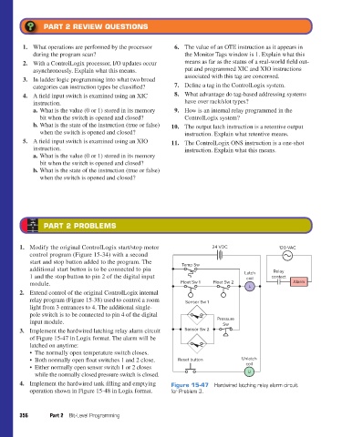
3. Implement the hardwired latching relay alarm circuit Sensor Sw 2
of Figure 15-47 in Logix format. The alarm will be
latched on anytime:
• The normally open temperature switch closes.
• Both normally open float switches 1 and 2 close. Reset button Unlatch
• Either normally open sensor switch 1 or 2 closes coil
while the normally closed pressure switch is closed. U
4. Implement the hardwired tank filling and emptying Figure 15-47 Hardwired latching relay alarm circuit
operation shown in Figure 15-48 in Logix format. for Problem 3.
356 Part 2 Bit-Level Programming
pet73842_ch15_333-394.indd 356 03/11/15 7:33 PM